Level:
Correct: 0
Incorrect: 0
Marks: 0/0
Exam Practice
Subject:
Topics:
AQA GCSE Physics Smart practice A mixed round aimed at your weak spots
Unit 1
Energy
Energy changes in a system, and the ways energy is stored before and after such changes
Energy stores and systems
0%
Changes in energy
0%
Energy changes in systems
0%
Power
0%
Conservation and dissipation of energy
Energy transfers in a system
0%
Efficiency
0%
Unit 2
Electricity
Unit 3
Particle model of matter
Unit 4
Atomic structure
Unit 5
Forces
Unit 6
Waves
Unit 7
Magnetism and electromagnetism
Unit 8
Space physics (physics only)
Avg
score:
–
Topics
done:
0/91

Standard circuit diagram symbols

Practise 18 exam-style questions on Standard circuit diagram symbols for AQA GCSE Physics. Write your answer as you would in the exam and get it marked in seconds against the mark scheme, point by point, with an AI tutor on hand if you get stuck.

  • 18 questions
  • 1–6 marks each
  • Instant marking
  • No sign-up needed
18 questions, marked as you go

Sample questions with model answers

Here are 4 of the questions in this topic, each with a model answer, an explanation of why it earns the marks and the mark scheme an examiner would use.

Question 1

2 marks

The circuit diagram shows two components, P and Q, connected in series with a battery and an ammeter.

Name component P and component Q.
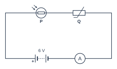
Circuit diagram. All the components are connected in series in a single loop. Going round the loop from the + terminal of the battery (labelled 6 V): component P (drawn as a small rectangle inside a circle, with two arrows pointing in towards the circle); then component Q (drawn as a rectangle with a diagonal line through it that ends in a short horizontal tail at the bottom); then an ammeter; and back to the − terminal of the battery.

Model answer

P is a light-dependent resistor (LDR).
Q is a thermistor.

Explanation

The LDR symbol is a resistor rectangle (often drawn inside a circle) with two arrows pointing in towards it, showing light falling on it. The thermistor symbol is a resistor rectangle with a diagonal line through it that has a short flat 'tail' at one end. Do not confuse the LDR with an LED, whose arrows point outwards because it gives out light.

Mark scheme
  1. 1 mark

    P: light-dependent resistor

    allow LDR; do not accept light-emitting diode / LED

  2. 1 mark

    Q: thermistor

    do not accept variable resistor
Question 2

2 marks

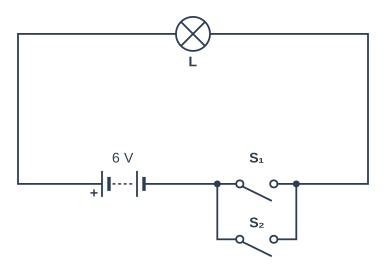
The circuit diagram shows the circuit for a light on a staircase. Lamp L is controlled by two switches, S₁ and S₂. Both switches are shown open.

Switch S₁ is closed and switch S₂ is left open.

Explain whether lamp L lights.

Circuit diagram. Going round the loop from the + terminal of the battery (labelled 6 V): lamp L; then two branches in parallel (one branch has switch S₁ (open); the other branch has switch S₂ (open)); and back to the − terminal of the battery.

Model answer

Lamp L lights. S₁ and S₂ are connected in parallel, so closing S₁ makes a complete loop through the branch containing S₁. Current flows through the lamp even though S₂ is still open.

Explanation

When two switches are in parallel, either one can complete the circuit. If they were in series, both would have to be closed for the lamp to light.

Mark scheme
  1. 1 mark

    the lamp lights

  2. 1 mark

    closing S₁ completes the circuit: current can flow through the branch containing S₁ (even though S₂ is open)

    allow the switches are in parallel, so only one needs to be closed

Question 3

3 marks

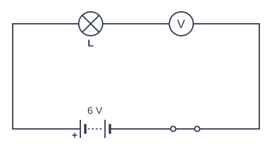
A student builds the circuit shown in the circuit diagram to measure the potential difference across lamp L. When the switch is closed, the lamp does not light.

Explain why the lamp does not light and describe how the voltmeter should be connected.

Circuit diagram. All the components are connected in series in a single loop. Going round the loop from the + terminal of the battery (labelled 6 V): lamp L; then a voltmeter; then a closed switch; and back to the − terminal of the battery.

Model answer

The voltmeter is in series with the lamp. A voltmeter has a very high resistance, so almost no current flows round the circuit and the lamp does not light. The lamp should be connected straight into the loop and the voltmeter connected in parallel with the lamp, one lead on each side of it.

Explanation

A voltmeter measures the potential difference between two points, so it is always connected across a component. Its very high resistance means it takes almost no current when connected in parallel, but in series it stops almost all of the current in the loop.

Mark scheme
  1. 1 mark

    the voltmeter is connected in series with the lamp

  2. 1 mark

    a voltmeter has a very high resistance, so the current is (very) small / almost zero

    allow so (almost) no current flows

  3. 1 mark

    the voltmeter should be connected in parallel with / across the lamp

    allow connected to each side of the lamp, with the lamp joined directly into the loop

Question 4

4 marks

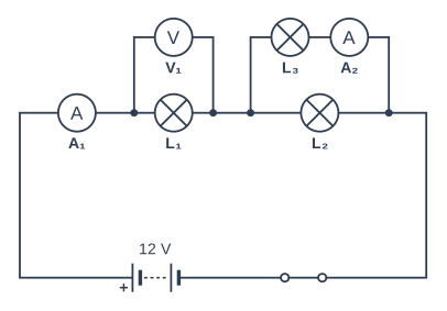
The circuit diagram shows three lamps, two ammeters and a voltmeter connected to a battery.

Give the label of:
• the meter that measures the total current from the battery
• the meter that measures the current in lamp L₃ only
• the lamp that voltmeter V₁ is connected across
• the lamp that is connected in parallel with lamp L₃.

Circuit diagram. Going round the loop from the + terminal of the battery (labelled 12 V): ammeter A₁; then lamp L₁, with voltmeter V₁ connected across it; then two branches in parallel (one branch has lamp L₂; the other branch has lamp L₃ then ammeter A₂); then a closed switch; and back to the − terminal of the battery.

Model answer

Total current from the battery: A₁
Current in L₃ only: A₂
Voltmeter V₁ is across: L₁
Lamp in parallel with L₃: L₂

Explanation

A₁ is in the main part of the circuit, before the current splits, so it measures the total current. A₂ is in series with L₃ on its own branch, so it measures only the current in L₃. A voltmeter measures the potential difference across the component it is connected in parallel with.

Mark scheme
  1. 1 mark

    A₁

  2. 1 mark

    A₂

  3. 1 mark

    L₁

  4. 1 mark

    L₂

Ready to try the rest? Every answer you write is marked against the mark scheme, so you can see exactly where the marks are.

AI Tutor Hints first, answers after you try

Hi! Stuck? Ask me for a hint and I’ll help you work it out. Once you’ve checked your answer I can explain exactly where the marks are.