
Level:
Correct: 0
Incorrect: 0
Marks: 0/0
Exam Practice
Course:
Topics:
AQA GCSE Design and Technology Smart practice A mixed round aimed at your weak spots
Unit 1
Core technical principles
Unit 2
Specialist technical principles
Unit 3
Designing and making principles
Investigation, primary and secondary data
Environmental, social and economic challenge
Design strategies
Design strategies
Communication of design ideas
Prototype development
Selection of materials and components
Selecting materials and components for prototypes
Specialist tools and equipment
Avg
score:
–
Topics
done:
0/40

Shaping and forming by cutting, abrasion and addition

Practise 21 exam-style questions on Shaping and forming by cutting, abrasion and addition for AQA GCSE Design and Technology. Write your answer as you would in the exam and get it marked in seconds against the mark scheme, point by point, with the Study Helper on hand if you get stuck.

  • 21 questions
  • 1–8 marks each
  • Instant marking
  • No sign-up needed
20 questions, marked as you go

Sample questions with model answers

Here are 4 of the questions in this topic, each with a model answer, an explanation of why it earns the marks and the mark scheme an examiner would use.

Question 1

1 mark

Omar is planing the end grain of a pine board with a smoothing plane. He planes from each edge towards the middle of the end, rather than straight across from one edge to the other.

Why does he do this?

Choose your answer.

  • To make the board shrink less as it dries
  • To keep the plane blade sharp for longer
  • To make the end grain absorb less glue
  • To stop the far corner of the board splitting off

Model answer

To stop the far corner of the board splitting off

Explanation

When a plane runs right across end grain, the fibres at the far edge have nothing behind them and break away, splitting off the corner. Planing in from each edge towards the middle, clamping a scrap block against the far edge, or cutting a small chamfer on the waste corner all prevent this. The wrong options mix up planing technique with seasoning, blade wear and gluing.

Mark scheme
  1. 1 mark

    To stop the far corner of the board splitting off

    If more than one option is given, 0 marks. The direction of planing has no effect on how much the board shrinks (that depends on its moisture content and seasoning). It does not keep the blade sharp; end grain blunts a blade whichever way it is planed. It has nothing to do with how much glue the end grain absorbs.
Question 2

2 marks

Dev is printing a model of a desk lamp in PLA on a fused deposition modelling (FDM) 3D printer. The lamp's arm sticks out horizontally from the stand.

Explain why the printing software adds supports under the arm.

Model answer

An FDM printer builds the model by laying melted filament in layers, each one deposited on top of the layer below. The horizontal arm is an overhang with nothing underneath it, so without supports the soft filament would droop or fall into the air and the arm would be misshapen or the print would fail. The supports give it something to be built on and are removed afterwards.

Explanation

3D printing is an addition process, so every layer must rest on the one beneath. Steep overhangs and bridges need temporary support material, which uses extra filament and time and leaves marks that may need sanding. Answers need both parts: how the layers are built and why the overhang would sag.

Mark scheme
  1. 1 mark

    The printer builds the model by adding layers of melted filament, each one deposited on top of the layer below

    Accept 'it is an additive process: each layer needs something underneath to be printed on'.

  2. 1 mark

    The horizontal arm (an overhang) has nothing under it, so without supports the soft, hot filament would sag, droop or fall, spoiling the shape or causing the print to fail

    Accept that overhangs beyond about 45° from vertical need support. Do not accept 'to make it stronger' or 'to hold the model in place while it cools' alone. Saying the supports are snapped off afterwards is true but earns no mark on its own.

Question 3

3 marks

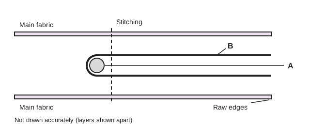
The diagram shows a cross-section through a piped seam on a cushion cover, as it is being sewn. Strip B is cut on the bias, at 45° to the grain of the fabric.

Name the part labelled A.

Explain why strip B is cut on the bias.

A cross-section through a piped seam, with the layers drawn slightly apart. A layer of main fabric runs along the top and another along the bottom. Between them, a strip labelled B is folded round a small circular part labelled A, with both ends of the strip running to the right to finish level with the raw edges of the main fabric. A dashed vertical line labelled 'Stitching' passes through all the layers just to the right of part A. The raw edges are labelled at the right. Not drawn accurately.

Model answer

A is the piping cord.
Strip B is cut on the bias because fabric cut at 45° to the grain stretches more than fabric cut on the straight grain. This lets the strip wrap smoothly round the cord and bend round the corners and curves of the cushion without puckering or wrinkling.

Explanation

Piping is made by folding a bias strip round a cord and stitching it into a seam close to the cord, giving a firm, decorative edge that also protects the seam from wear. Woven fabric barely stretches along its warp and weft, but it gives on the diagonal, which is why bias strips are used for piping and binding curved edges. 'It looks neater' does not explain why the bias is needed.

Mark scheme
  1. 1 mark

    A: piping cord / cord

    Accept 'filler cord'. Do not accept 'thread', 'string' or 'wadding'.

  2. 1 mark

    Fabric cut on the bias has more stretch / give than fabric cut along the straight grain

    Do not accept 'it is stronger' or 'it uses less fabric' or 'it looks better' alone.

  3. 1 mark

    So the strip can bend smoothly round the curves and corners of the cushion and wrap round the cord without puckering, wrinkling or pulling

    Accept 'so it lies flat and smooth around curved edges'.

Question 4

6 marks

Choose one of the following tasks:

- brazing two pieces of 3 mm mild steel strip together at a right angle on a brazing hearth
- making a small circuit on an etched printed circuit board (PCB): cutting the board to size, drilling the holes and soldering in a resistor and an LED
- bending a strip of 3 mm acrylic to 90° on a line bender (strip heater) to make a phone stand.

Describe, in a logical sequence, how the task is carried out. Name the equipment used.

Model answer

I have chosen bending acrylic on a line bender.

First I mark the bend line on the acrylic with a non-permanent marker and peel off the protective film. I switch on the line bender and let the heating element warm up fully.

I place the acrylic across the bender so the marked line is directly over the element. I turn the strip over every 30 seconds or so, so that both sides heat evenly along the line. I keep testing it gently; when it is flexible along the line I stop heating, before it starts to bubble or scorch.

Wearing heat-resistant gloves, I bend the acrylic to 90° against a wooden former or bending jig that has a square corner, and hold it there until it cools and sets. I can speed this up with a damp cloth. Finally I check the angle with a try square. The work is done in a ventilated area, and I never touch the heating element.

Explanation

Top-level answers give the stages in the right order, name specific equipment (brazing hearth, fire bricks, borax flux, brazing rod; PCB drill, soldering iron, side cutters; line bender, former, try square) and say how accuracy and safety are achieved at each step. Answers that only list safety points, or mix up stages (for example soldering before drilling, or melting the rod in the flame instead of on the hot joint), stay in Level 1 or 2.

Mark scheme
  1. 6 marks

    Levels of response (6 marks).
    Level 3 (5-6 marks): A detailed description making several correct points for the selected process. Specific correct and appropriate process stages and specific equipment given, in a logical sequence.
    Level 2 (3-4 marks): A description with points showing some understanding of the selected process. Basic reference made to some stages of the process with some equipment given.
    Level 1 (1-2 marks): Simple notes showing limited understanding of the selected process.
    0 marks: No response or nothing worthy of credit.

    Indicative content (illustrative, not exhaustive; credit any worthy points made in support of the band descriptors): BRAZING: cut and file the strips so the joint faces fit closely; clean and degrease the joint area with emery cloth or a file (brazing will not take on rust, scale or grease); set the parts at 90° on fire bricks in the brazing hearth, held with more fire bricks or a clamp or wire, checked with a try square; mix borax flux with water to a paste and apply it to the joint (it stops oxidation and helps the brass flow); light the gas/air torch with the flame pointing away, wearing goggles, a leather apron and heat-resistant gloves or gauntlets; heat the whole joint area evenly, including the thicker part, to bright red (about 850-900 °C); dip the warm brazing rod (brass spelter) in flux and touch it on the joint so that the heat of the steel, not the flame alone, melts the rod and the brass flows into the joint by capillary action; remove the heat and let the joint cool below red heat on the hearth, handling it with tongs, before quenching in water; clean off the hard flux residue with a file, wire brush or pickling solution; ventilation or extraction for fumes; warn others that the metal is hot (chalk 'HOT'). PCB: wear goggles; cut the board along the marked lines with a PCB guillotine or junior hacksaw and file or sand the edges; drill the holes at the centre of each pad with a 1 mm HSS bit in a PCB drill or small pillar drill, with the board supported and held; dust from cutting and drilling glass-fibre board is an irritant, so use extraction or a dust mask; clean the copper with a PCB eraser or fine abrasive; fit the resistor (either way round) and the LED the correct way (longer leg/anode to positive, flat side/cathode to negative); bend the legs slightly to hold them; switch on the soldering iron, keep it in its stand, clean and tin the tip on a damp sponge; heat the pad and the leg together, feed solder onto the joint (not the iron), remove the solder then the iron; joint should be shiny and cone shaped; trim the legs with side cutters, holding the leg; use fume extraction and wash hands; check for bridges and dry joints. LINE BENDING: mark the bend line with a non-permanent marker; remove the protective film; switch on the line bender and let it warm up; put the acrylic over the heating element with the line directly above it; turn the strip over regularly so it heats evenly; test until it is flexible along the line, not bubbling or scorched (overheated); bend to 90° against a former, jig or square block of wood; hold it in place until it cools and sets (a damp cloth may be used); wear heat-resistant gloves and work in a ventilated area; check the angle with a try square. Accept all other valid responses.

Ready to try the rest? Every answer you write is marked against the mark scheme, so you can see exactly where the marks are.

Study Helper Hints first, answers after you try

Stuck on this one? Ask for a hint and I’ll point you in the right direction, without giving the answer away. Once you’ve checked your answer, I’ll show you how the marks are awarded.