Practise 20 exam-style questions on Production aids and cutting to a tolerance for AQA GCSE Design and Technology. Write your answer as you would in the exam and get it marked in seconds against the mark scheme, point by point, with the Study Helper on hand if you get stuck.
20 questions
1–8 marks each
Instant marking
No sign-up needed
20 questions, marked as you go
Sample questions with model answers
Here are 4 of the questions in this topic, each with a model answer, an explanation of why it earns the marks and the mark scheme an examiner would use.
Question 1
1 mark
In sand casting, a wooden replica of the product is packed in moulding sand and then removed, leaving a cavity into which molten aluminium is poured.
What is this replica called?
Choose your answer.
core
former
runner
pattern
Model answer
pattern
Explanation
A casting pattern is a production aid: one pattern can make many identical moulds, so every casting is the same shape. Patterns are made slightly larger than the finished casting to allow for the metal shrinking as it cools, and with slightly tapered sides (draft) so they can be drawn out of the sand without damaging the mould.
Mark scheme
1 mark
pattern
If more than one option is given, 0 marks. A core is a separate sand shape placed in the mould to form a hole or hollow inside the casting. A former is a shape used to bend or form sheet or strip materials (e.g. for laminating or vacuum forming). A runner is a channel in the mould that carries the molten metal from the sprue to the cavity.
Question 2
3 marks
A printer prints a batch of A5 leaflets several to a sheet on large sheets of paper. The leaflets have a coloured background that goes right up to their edges.
Explain how crop marks and bleed help the printer to cut the leaflets accurately to size.
Model answer
Crop marks are short, thin lines printed at the corners of each leaflet, outside the area of the finished leaflet. They show the printer exactly where to cut, so the guillotine blade can be lined up with them and every leaflet is trimmed to the same A5 size; because they are outside the leaflet they are cut away. Bleed means the coloured background is printed about 3 mm beyond the cut line, so if the cut is very slightly out there is still colour right to the edge and no white strip shows.
Explanation
Crop marks are reference points for cutting, and bleed gives a tolerance for that cut, so the leaflets look right even if the guillotine is a fraction of a millimetre out. Top answers explain both where to cut (crop marks) and why a small error does not show (bleed). Saying only that crop marks show where to cut earns one mark.
Mark scheme
1 mark
crop marks are fine lines printed at the corners, outside the leaflet area, that show exactly where the sheet is to be cut (trimmed)
One mark for each valid point, max 3. A point explained in detail (e.g. what crop marks are and how they are used to set the cut) may earn 2 marks.
1 mark
the guillotine blade is lined up with the crop marks, so every leaflet is trimmed to the same finished size (148 × 210 mm)
1 mark
crop marks are outside the finished leaflet, so they are cut away and do not show on the product
1 mark
bleed: the background is printed slightly beyond the cut line (usually about 3 mm)
1 mark
so if the cut is very slightly out there is no thin white strip along the edge of the leaflet
Also credit: lining up the crop marks through a stack of sheets checks that the stack is square before it is cut. Do not credit 'bleed is where the ink runs'. Accept all other valid responses.
Question 3
3 marks
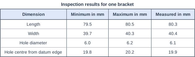
A batch of laser-cut acrylic brackets is inspected. The table shows the minimum and maximum sizes allowed for four dimensions of one bracket, and the sizes measured on it.
State whether this bracket is acceptable. Identify any dimension that is outside its limits and state by how much it is outside.
Model answer
The bracket is not acceptable. Its width is 40.4 mm, which is 0.1 mm above the maximum of 40.3 mm. The length (80.3 mm), hole diameter (6.1 mm) and hole position (19.9 mm) are all within their limits, but one dimension outside its limits means the bracket must be rejected.
Explanation
Each measured size is compared with both of its limits: it is acceptable only if it lies between the minimum and the maximum (a size equal to a limit still passes). One dimension outside its limits is enough to reject a part, because it may not fit or work with the parts it joins. A common slip is to check only one limit.
Mark scheme
1 mark
the width (40.4 mm) is above its maximum of 40.3 mm
Mark the numbers, not the units. If the student also wrongly states that the length, hole diameter or hole position is outside its limits, max 2.
1 mark
by 0.1 mm
1 mark
so the bracket is not acceptable / must be rejected (the other three dimensions are within their limits)
A statement that the bracket is not acceptable earns this mark even if the reason is incomplete.
Question 4
5 marks
Choose one of these processes: - cutting pine to length on a mitre saw using an end stop - filing the edges of a mild steel bracket to a scribed outline - cutting out a card box net by hand with a craft knife and scoring its fold lines - drilling the holes in a PCB.
Describe in detail how your chosen process is carried out so that the material is cut, shaped or formed to a tolerance.
Model answer
Chosen process: cutting pine to length on a mitre saw using an end stop. First I check that the saw is set to 0° using a try square against the blade and fence, then trim one end of the pine square to give a reference end. I measure the required length, for example 300 mm, from the edge of the teeth facing the stop, so that the saw cut (kerf) is in the waste and not taken off the piece, and clamp the end stop at that distance. I hold the timber firmly against the fence with the squared end against the stop, let the blade reach full speed and lower it steadily through the wood. I measure this first piece with a steel rule; if it is outside the tolerance (for example 300 ± 0.5 mm) I adjust the stop and cut another test piece. Once it is within tolerance, every length is pushed against the stop before cutting, so all pieces are the same length. I brush sawdust away from the stop, because a build-up would make pieces shorter, and check every tenth piece. The guard stays in place, I wear goggles and keep my hands well away from the blade.
Explanation
The top level needs a clear sequence of the chosen process and specific detail of how the tolerance is achieved and checked - setting stops or datums, allowing for the kerf, using templates, removing the last of the waste carefully, test pieces and measuring tools. Common pitfalls are describing the process with no reference to accuracy, or listing safety points only.
Mark scheme
5 marks
Levels of response (5 marks). Level 5 (5 marks): Fully coherent response using detailed notes with clear understanding of how the chosen process is used correctly to cut, shape or form the material to a tolerance. Level 4 (4 marks): Clear notes used to correctly explain the chosen process and a simple attempt to consider how a tolerance might be achieved during the process. Level 3 (3 marks): Notes used correctly to explain the chosen process with implied reference to use of a tolerance. Level 2 (2 marks): Simple notes demonstrating a very basic understanding of the chosen process. Level 1 (1 mark): Simple note related to the chosen process. 0 marks: No response or nothing worthy of credit.
Indicative content (illustrative, not exhaustive; credit any worthy points made in support of the band descriptors). Mitre saw: square one end first as the reference end; check the blade angle (0° or 45°) with a try square or mitre square; measure the length from the side of the teeth facing the stop so the kerf falls in the waste; clamp the end stop at that distance; hold the timber firmly against the fence; let the blade reach full speed and lower it steadily; cut a test piece and measure it with a steel rule or tape, adjusting the stop until it is within tolerance (e.g. ±0.5 mm); butt every piece against the stop, clearing sawdust from the stop; check sample pieces through the batch; guard in place, goggles, hands clear. Filing mild steel: coat with marking blue and scribe the outline from datum edges with a scriber, steel rule and engineer's square (odd-leg calipers for lines parallel to an edge); hacksaw on the waste side about 1 mm from the line; hold the work low in a vice with soft jaws so it does not vibrate; cross file with a coarser (bastard or second cut) file to remove most of the waste, then a smooth file for the last few tenths of a millimetre, stopping exactly at the line; draw file for a straight, smooth edge; check often with an engineer's square (squareness), a straight edge (flatness) and a steel rule or vernier caliper (size, e.g. 60 ± 0.2 mm); deburr; file handle fitted, brush filings away rather than blowing them. Card net: square a datum edge and mark out from it with a sharp pencil, steel rule and set square, or draw round a template so every net matches (e.g. to ±0.5 mm); different line types for cut and fold lines; on a cutting mat, cut with a sharp craft knife against a steel safety rule, blade upright and exactly on the line, in several light passes; score the fold lines against the rule with a scoring tool or the back of the blade so the card folds exactly on the line without cutting through; check panel sizes with a rule and dry-fold to check that edges meet and tabs fit; replace blunt blades, which tear the card; fingers behind the rule's guard, retract the blade after use. PCB drilling: drill after etching, using the small hole etched in the centre of each copper pad as a centre mark; use a PCB drill on a stand with a fine bit (about 0.8-1.0 mm for component leads, larger for mounting holes); keep the drill perpendicular and centred so the pad ring is not broken; drill onto scrap wood to avoid breakout; check that DIL IC pins (2.54 mm pitch) and leads fit before soldering; goggles and dust control. To reach Level 4-5 the response must show how the tolerance is achieved (stops, datums, templates, removing the last of the waste in small steps, checking with measuring tools). Accept all other valid responses.
Ready to try the rest? Every answer you write is marked against the mark scheme, so you can see exactly where the marks are.
Ctrl + Enter to check
Study HelperHints first, answers after you try
Stuck on this one? Ask for a hint and I’ll point you in the right direction, without giving the answer away. Once you’ve checked your answer, I’ll show you how the marks are awarded.