Level:
Correct: 0
Incorrect: 0
Marks: 0/0
Exam Practice
Course:
Topics:
AQA GCSE Engineering Smart practice A mixed round aimed at your weak spots
Unit 1
Engineering materials
Unit 2
Engineering manufacturing processes
Additive manufacturing
Material removal
Material removal
Casting and moulding
Joining and assembly
Heat and chemical treatment
Surface finishing
Surface finishing
Unit 3
Systems
Unit 4
Testing and investigation
Unit 5
The impact of modern technologies
Unit 6
Practical engineering skills
Avg
score:
–
Topics
done:
0/32

Systems descriptions

Practise 12 exam-style questions on Systems descriptions for AQA GCSE Engineering. Write your answer as you would in the exam and get it marked in seconds against the mark scheme, point by point, with the Study Helper on hand if you get stuck.

  • 12 questions
  • 1–8 marks each
  • Instant marking
  • No sign-up needed
12 questions, marked as you go

Sample questions with model answers

Here are 4 of the questions in this topic, each with a model answer, an explanation of why it earns the marks and the mark scheme an examiner would use.

Question 1

1 mark

An electric toaster heats bread for a time set on a dial. It does not measure how brown the bread is.

Which type of control system is this?

Choose your answer.

  • A Closed-loop
  • B Feedback
  • C Open-loop
  • D Sub-system

Model answer

C Open-loop

Explanation

An open-loop system carries out its process (heating for a set time) without measuring the result, so there is no feedback. A closed-loop system measures its output and feeds this back to adjust what it does, for example a toaster with a sensor that stops when the bread is the right colour.

Mark scheme
  1. 1 mark

    C / Open-loop

    Accept the letter or the option text. If more than one option is given, 0 marks.

Question 2

2 marks

An electric scooter is designed as several sub-systems, such as the battery pack, the motor controller and the braking system.

Give two reasons why engineers divide a complex product into sub-systems.

Model answer

1. Each sub-system can be designed and tested separately by a specialist team, so the work can be done at the same time.
2. If a part fails, the faulty sub-system (for example the battery pack) can be found quickly and replaced as a whole unit.

Explanation

Breaking a system into sub-systems (each with its own inputs, processes and outputs) makes a complex product manageable. Teams can work in parallel, test each block, find faults more easily and swap whole modules for repair or reuse. Each different reason earns 1 mark; vague answers such as 'it is easier' do not score.

Mark scheme
  1. 2 marks

    Any two different reasons: different specialist teams can design each sub-system at the same time / each sub-system can be tested on its own before the product is assembled / faults are easier to find / a faulty sub-system can be replaced as a whole module, making repair and maintenance easier / sub-systems can be reused in other products or bought in as standard parts / it makes a complex system easier to understand and design

    1 mark for each different correct reason, max 2. Do not accept 'easier' or 'quicker' with no reason, or reasons that repeat the same idea (e.g. 'easier to repair' and 'easier to fix').

Question 3

2 marks

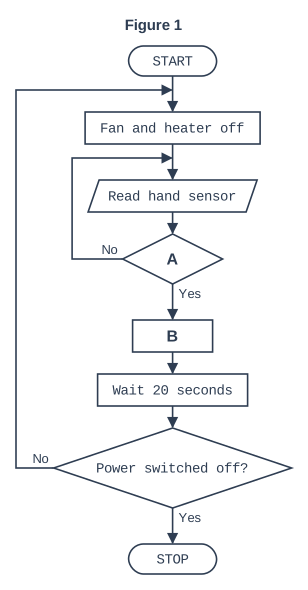
Figure 1 shows a flowchart for an automatic hand dryer. Each time hands are placed under the dryer, the fan and heater must switch on for 20 seconds and then switch off.

State what should be written in box A and in box B.

Figure 1. Flowchart, read from the top. START, then the process box "Fan and heater off", then the input/output box "Read hand sensor", then decision box A (if No, the flow line goes back up to the input/output box "Read hand sensor"; if Yes, the loop ends), then process box B, then the process box "Wait 20 seconds", then the decision box "Power switched off?" (if No, the flow line goes back up to the process box "Fan and heater off"; if Yes, the loop ends). After the loop: STOP.

Model answer

Box A: Hands detected?
Box B: Fan and heater on

Explanation

Box A is a decision: the program keeps reading the sensor and loops back until hands are detected (the Yes exit leaves the loop). Box B is a process box that switches on the outputs. It must come before the 'Wait 20 seconds' box, so the fan and heater run for 20 seconds before the program loops back to switch them off.

Mark scheme
  1. 1 mark

    A: Hands detected? / Are hands under the dryer?

    Must be a question (decision) about hands being detected. Accept 'Sensor on?' or 'Is the sensor triggered?'.

  2. 1 mark

    B: Fan and heater on / Switch on fan and heater

    Both the fan and the heater must be switched on. 'Fan on' alone scores 0.

Question 4

6 marks

A farm stores drinking water for its animals in a large tank. The tank must refill automatically when the water falls to a low level, and stop filling when it is full.

Use notes to describe a system that would do this. Your answer should:
- name the input, process and output sub-systems
- describe what each sub-system does
- explain how feedback is used.

Model answer

Input: Two float switches are fixed inside the tank, one near the bottom (low level) and one near the top (full level). Each switch changes state when the water reaches it, so the system always knows whether the water is below the low level, between the two, or full.

Process: A control unit (microcontroller) reads the signals from the float switches and compares the water level with the set levels. When the low-level switch shows the water has fallen too far, it decides to start filling; when the full-level switch is reached, it decides to stop. Because the pump needs a large current, the controller switches it on and off through a relay.

Output: An electric pump draws water from a borehole or the mains and pumps it into the tank. A warning lamp could also be lit if the tank has not filled after a set time, which would show a pump fault.

Feedback: As the pump runs, the water level rises. The full-level float switch detects this result of the output and feeds it back to the controller, which then switches the pump off. As the animals drink, the level falls until the low-level switch tells the controller to start the pump again. This closed loop keeps the tank topped up without anyone checking it, and using two levels stops the pump switching on and off every few seconds.

Explanation

A top answer names a suitable input (level sensors), process (a controller that compares the level with set values and switches the pump) and output (a pump or valve), describes what each does, and explains feedback: the result of the output (the rising water level) is measured and used to stop the filling. A simple float valve (ballcock) is also a valid closed-loop system. A list of parts with no description is capped at 2 marks.

Mark scheme
  1. 6 marks

    Levels of response (6 marks).
    Level 3 (5-6 marks): Detailed description of the whole system, including the input, process and output sub-systems, what each one does and how feedback keeps the tank topped up. Notes are clear and in a logical order.
    Level 2 (3-4 marks): Some sub-systems described in detail OR the majority of sub-systems named but with insufficient detail to show how the system would work.
    Level 1 (1-2 marks): One or more basic parts of the system listed.
    0 marks: No response or nothing worthy of credit.

    Max 2 if the sub-systems are only named with no description. Max 4 if feedback is not explained.
    Indicative content (accept all other valid responses):
    - Input: water level sensors, e.g. float switches or probes at the low level and the full level, or an ultrasonic level sensor.
    - Process: a control unit (microcontroller) compares the measured level with the set low and full levels and decides when to start and stop filling; it switches the pump through a relay or driver.
    - Output: an electric pump (or a solenoid valve on the water supply) fills the tank; a warning lamp or buzzer if the tank does not fill (e.g. a pump fault).
    - Feedback: as the tank fills, the water level rises; the sensor detects the new level and, when the full level is reached, the controller switches the pump off. When the level falls to the low level again, the pump is switched back on (closed loop).
    - Using two levels stops the pump switching on and off constantly.
    - Power supply, e.g. mains, or a solar panel and battery in a field.
    - A mechanical solution is acceptable: a float on a lever arm (ballcock). The float (input) senses the water level, the lever (process) transfers and magnifies its movement, and a valve (output) opens to let water in when the float drops and closes as the float rises; the rising water itself is the feedback.

Ready to try the rest? Every answer you write is marked against the mark scheme, so you can see exactly where the marks are.

Study Helper Hints first, answers after you try

Stuck on this one? Ask for a hint and I’ll point you in the right direction, without giving the answer away. Once you’ve checked your answer, I’ll show you how the marks are awarded.