
Level:
Correct: 0
Incorrect: 0
Marks: 0/0
Exam Practice
Course:
Topics:
AQA GCSE Engineering Smart practice A mixed round aimed at your weak spots
Unit 1
Engineering materials
Unit 2
Engineering manufacturing processes
Additive manufacturing
Material removal
Material removal
Casting and moulding
Joining and assembly
Heat and chemical treatment
Surface finishing
Surface finishing
Unit 3
Systems
Unit 4
Testing and investigation
Unit 5
The impact of modern technologies
Unit 6
Practical engineering skills
Avg
score:
–
Topics
done:
0/32

Electrical systems

Practise 15 exam-style questions on Electrical systems for AQA GCSE Engineering. Write your answer as you would in the exam and get it marked in seconds against the mark scheme, point by point, with the Study Helper on hand if you get stuck.

  • 15 questions
  • 1–8 marks each
  • Instant marking
  • No sign-up needed
15 questions, marked as you go

Sample questions with model answers

Here are 4 of the questions in this topic, each with a model answer, an explanation of why it earns the marks and the mark scheme an examiner would use.

Question 1

1 mark

A security alarm uses a switch fitted to a window frame. A small magnet is fixed to the window. When the window is closed, the magnet sits next to the switch and holds its contacts closed. When the window is opened, the contacts spring apart.

Which type of switch is this?

Choose your answer.

  • A Micro switch
  • B Reed switch
  • C Rocker switch
  • D Tilt switch

Model answer

B Reed switch

Explanation

A reed switch has two thin metal contacts (reeds) sealed in a glass tube; a magnet brought near it makes the reeds touch, so it can sense a door or window without any physical contact. A micro switch needs to be pressed by a lever or plunger, a rocker switch is operated by hand and a tilt switch responds to being tipped over.

Mark scheme
  1. 1 mark

    B / Reed switch

    Accept the letter or the option text. If more than one option is given, 0 marks.
Question 2

2 marks

The light inside a fridge comes on when the door is opened and goes off when the door is closed. The light is controlled by a push-to-break switch fitted to the door frame.

Explain how the push-to-break switch controls the light.

Model answer

When the door is shut it pushes in the button of the push-to-break switch, which breaks the circuit, so no current flows and the light is off. When the door is opened the button is released, the contacts spring back together and complete the circuit, so the light comes on.

Explanation

A push-to-break switch is normally closed: pressing it breaks the circuit and releasing it makes the circuit again. That is exactly what a fridge light needs, because the closed door presses the switch. One mark is for the door closed (pressed, circuit broken) and one for the door open (released, circuit made).

Mark scheme
  1. 1 mark

    When the door is closed it presses the switch (button/plunger), which breaks the circuit (opens the contacts), so the light is off

    An answer that says pressing the switch turns the light on does not score this mark.

  2. 1 mark

    When the door is opened the switch is released, so its contacts close (spring back) and complete the circuit, so current flows and the light comes on

    Accept 'releasing the button makes the circuit'. Do not accept 'the switch turns the light on' with no link to the door opening and the switch being released.

Question 3

3 marks

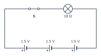
Figure 1 shows the circuit of a torch. It has three 1.5 V cells in series, a switch S and a lamp. When it is lit, the lamp has a resistance of 18 Ω.

Calculate the current through the lamp when switch S is closed.

Give your answer in amps.

Circuit diagram. All the components are connected in series in a single loop. The first cell is the one furthest right on the bottom wire. Going round the loop from the + terminal of the first cell (labelled 1.5 V): another cell labelled 1.5 V (connected the same way round as the first); then another cell labelled 1.5 V (connected the same way round as the first); then switch S (closed); then a lamp labelled 18 Ω; and back to the − terminal of the first cell.

Model answer

Total voltage = 3 × 1.5 = 4.5 V
I = V ÷ R = 4.5 ÷ 18 = 0.25 A

Explanation

Cells in series add their voltages, so the supply is 4.5 V, not 1.5 V. Ohm's law (V = I × R) rearranged gives I = V ÷ R, so the current is 4.5 ÷ 18 = 0.25 A. Common errors are using only one cell's voltage and multiplying instead of dividing.

Mark scheme
  1. 1 mark

    Total supply voltage = 3 × 1.5 = 4.5 V; or a correct final answer of 0.25 A with no working

    An answer of 0.25 A with no working scores 3 marks.

  2. 1 mark

    Ohm's law rearranged and substituted: I = V ÷ R = 4.5 ÷ 18

    Allow error carried forward (ECF): their voltage ÷ 18 scores this mark. Using one cell, 1.5 ÷ 18 = 0.083 A, scores 2 marks (this point and the next by ECF). 4.5 × 18 = 81 or 18 ÷ 4.5 = 4 scores only the first mark.

  3. 1 mark

    I = 0.25 A

    Accept 250 mA if the unit is given as mA. Allow ECF: their voltage ÷ 18 correctly worked out.

Question 4

6 marks

A relay allows a low-voltage control circuit to switch on a high-current motor circuit.

Use notes to explain how a relay works, from closing the switch in the control circuit to the motor starting, and then stopping again.

Model answer

1. When the switch in the low-voltage control circuit is closed, a small current flows through the relay's coil.
2. The coil is wound round a soft iron core, so it becomes an electromagnet.
3. The electromagnet attracts the soft iron armature, which pivots towards the coil.
4. As the armature moves it pushes the two switch contacts together (the normally open contacts close).
5. The closed contacts complete the separate motor circuit, so a much larger current flows from the motor's own supply and the motor starts.
6. When the control switch is opened, the current in the coil stops and the core loses its magnetism.
7. A return spring pulls the armature back, the contacts spring apart, the motor circuit is broken and the motor stops.
8. There is no electrical connection between the coil and the contacts, so the high-current motor circuit is isolated from the control circuit, which protects it and its user. A diode across the coil protects the control circuit from the voltage spike when the coil is switched off.

Explanation

Top answers follow the chain in order: current in the coil, electromagnet, armature attracted, contacts close, motor circuit completed, and then the reverse when the current stops (the spring returns the armature). Using the correct names of the parts and explaining that the two circuits are electrically separate lifts an answer to Level 3. A list such as 'coil, magnet, switch, motor' with no explanation of what happens stays in Level 1.

Mark scheme
  1. 6 marks

    Levels of response (6 marks).
    Level 3 (5-6 marks): Detailed explanation including all key stages of the relay's operation, from current in the coil to the motor circuit being made and then broken, using correct terms (coil, electromagnet, armature, contacts, spring), and the separation (isolation) of the two circuits. Notes are clear and in a logical order.
    Level 2 (3-4 marks): Some stages described in detail OR the majority of stages covered but with insufficient detail to explain how the relay switches the motor on and off.
    Level 1 (1-2 marks): One or more basic steps/stages listed.
    0 marks: No response or nothing worthy of credit.

    Max 2 if the stages are only listed with no detail.
    Indicative content (in order; accept all other valid responses):
    - The switch in the control circuit is closed, so a small current flows through the relay coil.
    - The coil (wound on a soft iron core) becomes an electromagnet / produces a magnetic field.
    - The electromagnet attracts (pulls) the soft iron armature, which pivots.
    - The moving armature pushes the switch contacts together (the normally open contacts close / common connects to NO).
    - This completes the separate motor circuit, so a larger current flows from the motor's own supply and the motor runs.
    - When the control switch is opened, the coil current stops and the magnetism is lost.
    - A spring pulls the armature back, the contacts open, the motor circuit is broken and the motor stops.
    - The control circuit and motor circuit are electrically separate, so the high voltage/current cannot reach the low-voltage circuit (safety); a diode is often fitted across the coil to protect the control circuit from the voltage spike when the coil is switched off.

Ready to try the rest? Every answer you write is marked against the mark scheme, so you can see exactly where the marks are.

Study Helper Hints first, answers after you try

Stuck on this one? Ask for a hint and I’ll point you in the right direction, without giving the answer away. Once you’ve checked your answer, I’ll show you how the marks are awarded.