Level:
Correct: 0
Incorrect: 0
Marks: 0/0
Exam Practice
Course:
Topics:
AQA GCSE Engineering Smart practice A mixed round aimed at your weak spots
Unit 1
Engineering materials
Unit 2
Engineering manufacturing processes
Additive manufacturing
Material removal
Material removal
Casting and moulding
Joining and assembly
Heat and chemical treatment
Surface finishing
Surface finishing
Unit 3
Systems
Unit 4
Testing and investigation
Unit 5
The impact of modern technologies
Unit 6
Practical engineering skills
Avg
score:
–
Topics
done:
0/32

Electronic inputs, signals and process devices

Practise 15 exam-style questions on Electronic inputs, signals and process devices for AQA GCSE Engineering. Write your answer as you would in the exam and get it marked in seconds against the mark scheme, point by point, with the Study Helper on hand if you get stuck.

  • 15 questions
  • 1–8 marks each
  • Instant marking
  • No sign-up needed
15 questions, marked as you go

Sample questions with model answers

Here are 4 of the questions in this topic, each with a model answer, an explanation of why it earns the marks and the mark scheme an examiner would use.

Question 1

1 mark

A bottling machine must stop its conveyor after 24 bottles have passed a sensor, so that a full crate can be removed.

Which process device would keep track of the number of bottles that have passed the sensor?

Choose your answer.

  • A Comparator
  • B Counter
  • C NOT gate
  • D Timer

Model answer

B Counter

Explanation

A counter adds one to its total each time it receives a pulse from the sensor, and can give an output when it reaches a set number (24 here). A timer measures a length of time, a comparator compares two voltages and a NOT gate inverts a signal.

Mark scheme
  1. 1 mark

    B / Counter

    Accept the letter or the option text. If more than one option is given, 0 marks.

Question 2

2 marks

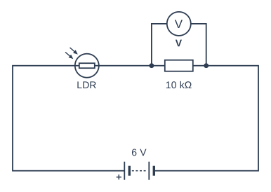
Figure 1 shows a light-sensing circuit made from a light dependent resistor (LDR) and a 10 kΩ fixed resistor connected to a 6 V battery. Voltmeter V measures the voltage across the fixed resistor.

Explain what happens to the reading on voltmeter V as the light level falls.

Circuit diagram. Going round the loop from the + terminal of the battery (labelled 6 V): an LDR (labelled "LDR"); then a resistor labelled 10 kΩ, with voltmeter V connected across it; and back to the − terminal of the battery.

Model answer

As it gets darker, the resistance of the LDR increases. The LDR then takes a bigger share of the 6 V supply (and less current flows through the fixed resistor), so the reading on voltmeter V goes down.

Explanation

The LDR and the fixed resistor form a potential divider: the 6 V is shared between them in proportion to their resistances. In the dark the LDR's resistance rises, so more of the voltage is across the LDR and less across the 10 kΩ resistor. This changing voltage is the sensor signal that a comparator or microcontroller can use.

Mark scheme
  1. 1 mark

    As the light level falls the resistance of the LDR increases

    Do not accept 'the LDR resistance decreases'.

  2. 1 mark

    So the LDR takes a larger share of the 6 V (less current flows), and the reading on V (the voltage across the fixed resistor) falls / decreases

    The answer must say that the reading on V decreases. Allow ECF: if the LDR resistance is said to decrease, 'so the reading on V increases' scores this mark.

Question 3

2 marks

An incubator for hatching hens' eggs is controlled by a microcontroller. Its thermistor temperature sensor is connected to one of the microcontroller's analogue (ADC) inputs rather than to a digital input pin.

Explain why the sensor is connected to an ADC input.

Model answer

The thermistor circuit gives an analogue voltage that rises and falls smoothly with temperature. The microcontroller can only process digital (binary) numbers, so the ADC converts the voltage into a number from 0 to 255. The program can then compare that number with set values for different temperatures, whereas a digital input pin would only read 'high' or 'low'.

Explanation

Sensors such as thermistors and LDRs give analogue signals, but a microcontroller works with digital numbers. An analogue to digital converter (ADC) turns the voltage into a number, so one input can tell many different temperatures apart and the switching points can be set in the program. Just restating 'it converts analogue to digital' earns little without saying why.

Mark scheme
  1. 1 mark

    The sensor gives an analogue signal: a voltage that varies continuously with temperature (over a range of values)

    Accept 'the thermistor gives a changing voltage, not just on or off'.

  2. 1 mark

    The ADC converts the voltage into a digital number (e.g. 0 to 255) that the program can process, so it can measure the actual temperature and compare it with set values; a digital input can only read high or low (1 or 0)

    Accept 'the microcontroller can only process digital (binary) data, so the analogue voltage must be converted'. Do not accept 'to convert analogue to digital' with no reason why that is needed.

Question 4

6 marks

A security light switches on for 2 minutes when a person moves in front of it, but only when it is dark. The electronic system uses:
- a light dependent resistor (LDR) with a comparator
- a passive infrared (PIR) movement sensor
- an AND gate
- a 555 timer
- a transistor that switches the lamp.

Use notes to explain how the system works, from the sensors to the lamp switching on and then off.

Model answer

1. The LDR is connected in series with a resistor as a potential divider. As daylight fades, the LDR's resistance rises, so the voltage from the divider changes gradually (an analogue signal).
2. The comparator compares this voltage with a reference voltage set by a variable resistor. When it is dark enough, the comparator's output switches to logic 1.
3. The PIR sensor detects the heat (infrared) given off by a moving person and its output goes to logic 1.
4. Both signals go into the AND gate, which gives 1 only when it is dark AND someone is moving, so the light never comes on in daylight.
5. The output of the AND gate triggers the 555 timer in monostable mode. Its output goes high for a fixed time, 2 minutes, set by its resistor and capacitor values.
6. The timer output can only give a small current, so it is connected to a transistor driver. The transistor switches on and lets the much larger lamp current flow, so the lamp lights.
7. When the 2 minutes are up, the timer output goes low, the transistor switches off and the lamp goes out. If the person moves again, the timer is re-triggered.

Explanation

Level 3 answers follow the signal through the system in order and say what each part does: sensing (LDR and PIR), deciding (comparator and AND gate), timing (555) and driving the output (transistor). Explaining why each part is needed, such as the AND gate stopping the lamp in daylight and the transistor supplying the lamp current, shows detailed understanding. Naming the parts without saying what they do stays in Level 1.

Mark scheme
  1. 6 marks

    Levels of response (6 marks).
    Level 3 (5-6 marks): Detailed explanation including all key stages from sensing to the lamp switching on and off, with the function of each component (sensors, comparator, AND gate, timer, transistor) and the signals passed between them. Notes are clear and in a logical order.
    Level 2 (3-4 marks): Some stages described in detail OR the majority of stages covered but with insufficient detail to explain how the system operates.
    Level 1 (1-2 marks): One or more basic steps/stages listed.
    0 marks: No response or nothing worthy of credit.

    Max 2 if the stages are only listed with no detail.
    Indicative content (in order; accept all other valid responses):
    - The LDR is in a potential divider with a resistor; as it gets darker its resistance rises and the voltage it gives changes (an analogue signal).
    - The comparator compares this voltage with a reference voltage (set by a variable resistor) and its output switches to 1 (high) when it is dark enough.
    - The PIR sensor detects the infrared from a moving person and gives a 1 (high) output.
    - The AND gate gives a 1 only when both inputs are 1: it is dark AND movement is detected (so the light does not come on in daylight).
    - The AND output triggers the 555 timer (monostable), whose output goes high for a set time (2 minutes, set by its resistor and capacitor).
    - The timer cannot supply enough current for the lamp, so its output switches on a transistor (driver), which allows a larger current to flow through the lamp (or a relay for a mains lamp).
    - After 2 minutes the timer output goes low, the transistor switches off and the lamp goes out, unless the PIR is triggered again.

Ready to try the rest? Every answer you write is marked against the mark scheme, so you can see exactly where the marks are.

Study Helper Hints first, answers after you try

Stuck on this one? Ask for a hint and I’ll point you in the right direction, without giving the answer away. Once you’ve checked your answer, I’ll show you how the marks are awarded.