
Level:
Correct: 0
Incorrect: 0
Marks: 0/0
Exam Practice
Course:
Topics:
AQA GCSE Engineering Smart practice A mixed round aimed at your weak spots
Unit 1
Engineering materials
Unit 2
Engineering manufacturing processes
Additive manufacturing
Material removal
Material removal
Casting and moulding
Joining and assembly
Heat and chemical treatment
Surface finishing
Surface finishing
Unit 3
Systems
Unit 4
Testing and investigation
Unit 5
The impact of modern technologies
Unit 6
Practical engineering skills
Avg
score:
–
Topics
done:
0/32

CNC, CAM and production planning

Practise 14 exam-style questions on CNC, CAM and production planning for AQA GCSE Engineering. Write your answer as you would in the exam and get it marked in seconds against the mark scheme, point by point, with the Study Helper on hand if you get stuck.

  • 14 questions
  • 1–8 marks each
  • Instant marking
  • No sign-up needed
14 questions, marked as you go

Sample questions with model answers

Here are 4 of the questions in this topic, each with a model answer, an explanation of why it earns the marks and the mark scheme an examiner would use.

Question 1

1 mark

Engineers use iconic, analogue and symbolic models to predict how a product will perform.

Which one of the following is an example of a symbolic model?

Choose your answer.

  • A A card scale model of a footbridge, made to show a client its appearance
  • B A spreadsheet that uses formulae to calculate the stress in each beam of a footbridge
  • C An electrical circuit used to imitate the flow of water through a system of pipes
  • D A 3D printed prototype of a bracket

Model answer

B

Explanation

A symbolic model represents a system with mathematical symbols, equations and calculations, such as a spreadsheet of formulae. Iconic models look like the real thing, such as a scale model (A) or a 3D printed prototype (D). An analogue model uses one system that behaves in the same way to represent another, such as an electrical circuit imitating water flow (C).

Mark scheme
  1. 1 mark

    B / A spreadsheet that uses formulae to calculate the stress in each beam of a footbridge

    Accept the letter or the option text. If more than one option is given, 0 marks.
Question 2

2 marks

A prototype circuit board is to be made by PCB routing on a small CNC machine, rather than by chemical etching.

Give two advantages of using PCB routing for the prototype.

Model answer

1. No etching chemicals are used, so there are no corrosive liquids to handle or dispose of safely.
2. The machine can also drill all the component holes in the same set-up, straight from the CAD layout.

Explanation

PCB routing (isolation milling) uses a small cutter to remove copper around each track, following tool paths made from the CAD layout, and then drills the holes. This avoids the chemical stages of etching (masking, exposing, developing and etching), which is useful for one-off prototypes. Etching is still faster per board for larger batches.

Mark scheme
  1. 2 marks

    Any two from: no hazardous etching chemicals (e.g. ferric chloride) to handle or dispose of / the component holes can be drilled on the same machine in the same set-up / it works directly from the CAD PCB layout, with no mask or UV exposure needed / quick for a single prototype / accurate and repeatable / less mess and fewer process stages

    1 mark for each different correct advantage, max 2. Do not accept 'faster' or 'easier' on their own; they must be linked to a reason (e.g. no mask needed).

Question 3

3 marks

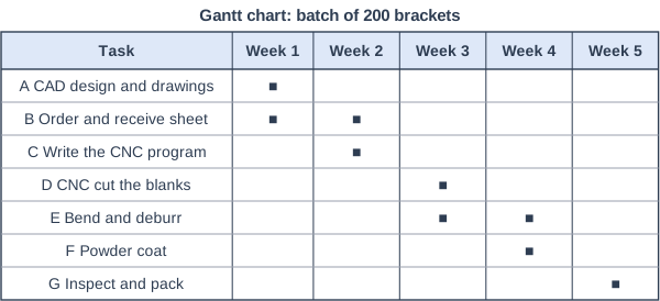
The Gantt chart shows the production plan for a batch of 200 brackets. A ■ shows the weeks in which each task takes place.

The supplier tells the company that the aluminium sheet (task B) will arrive one week late, so task B will end in week 3.

State the week in which the batch will now be finished, and explain your answer.

Gantt chart: batch of 200 brackets. Table with columns "Task", "Week 1", "Week 2", "Week 3", "Week 4", "Week 5". Task: A  CAD design and drawings; Week 1: ■; Week 2: (blank); Week 3: (blank); Week 4: (blank); Week 5: (blank) | Task: B  Order and receive sheet; Week 1: ■; Week 2: ■; Week 3: (blank); Week 4: (blank); Week 5: (blank) | Task: C  Write the CNC program; Week 1: (blank); Week 2: ■; Week 3: (blank); Week 4: (blank); Week 5: (blank) | Task: D  CNC cut the blanks; Week 1: (blank); Week 2: (blank); Week 3: ■; Week 4: (blank); Week 5: (blank) | Task: E  Bend and deburr; Week 1: (blank); Week 2: (blank); Week 3: ■; Week 4: ■; Week 5: (blank) | Task: F  Powder coat; Week 1: (blank); Week 2: (blank); Week 3: (blank); Week 4: ■; Week 5: (blank) | Task: G  Inspect and pack; Week 1: (blank); Week 2: (blank); Week 3: (blank); Week 4: (blank); Week 5: ■.

Model answer

The batch will now be finished in week 6. Task D, CNC cutting the blanks, cannot start until the sheet arrives, so it moves from week 3 to week 4. Bending (E), powder coating (F) and inspecting and packing (G) all follow on from cutting, so each moves back one week and packing finishes in week 6 instead of week 5. Tasks A and C do not need the sheet, so they are not affected.

Explanation

A Gantt chart shows when each task happens and which tasks run at the same time. When a task that others depend on is delayed, every task that follows it in the chain is delayed too, so the finish date moves back. Tasks that do not depend on it, such as writing the CNC program, can carry on as planned.

Mark scheme
  1. 1 mark

    Week 6

    An answer of week 6 with no explanation scores 1 mark.

  2. 1 mark

    Task D (CNC cutting) cannot start until the sheet has arrived, so it moves back one week (to week 4)

    Accept 'cutting depends on the material arriving'.

  3. 1 mark

    Tasks E, F and G each follow on from D, so they also move back one week, and G (inspect and pack) ends in week 6; tasks A and C are not affected

    Accept 'everything after task B is delayed by a week'. Do not accept 'every task is delayed' (A and C are not delayed).

Question 4

6 marks

A student has drawn a design for a set of 3 mm acrylic coasters in 2D CAD software.

Describe, in stages, how the coasters would be cut out on a laser cutter, from the CAD drawing to the finished parts.

Model answer

1. In the CAD software, check every coaster outline is a closed vector shape. Set the outlines to the cut colour (for example a red hairline) and any decoration to the engrave colour.
2. Arrange the coasters close together within the size of the sheet to reduce waste, then export the file as a DXF to the laser software.
3. Check the sheet is acrylic, not PVC, which gives off toxic fumes, and measure that it is 3 mm thick.
4. Lay the sheet flat on the honeycomb bed and line it up with the top left corner (the origin).
5. Set the focus height using the focus gauge so the laser is sharply focused on the surface.
6. Choose the stored settings for 3 mm acrylic, for example high power and low speed for cutting and lower power for engraving, and test on a scrap piece.
7. Turn on the fume extractor and air assist and close the lid, then start the job.
8. Stay and watch the laser for the whole job, ready to press the emergency stop if a flame appears.
9. When it finishes, wait for the fumes to be extracted, open the lid, lift out the coasters, check they have cut right through, peel off the protective film and remove the scrap from the bed.

Explanation

Top answers follow the whole CAD-to-CAM sequence: preparing the drawing (cut and engrave settings, nesting, export), setting up the machine (material check, sheet position, focus, power and speed) and running it safely (extraction, closed lid, never unattended, waiting for fumes). Missing either the machine set-up or the safety stages keeps an answer out of the top level, and a bare list scores no more than 2.

Mark scheme
  1. 6 marks

    Levels of response (6 marks).
    Level 3 (5-6 marks): Detailed explanation including all key stages to cut out the coasters from the CAD drawing, with the equipment/software settings used and safety. Notes are clear and in a logical order.
    Level 2 (3-4 marks): Some stages described in detail OR the majority of stages covered but with insufficient detail to allow the coasters to be cut out correctly.
    Level 1 (1-2 marks): One or more basic steps/stages listed.
    0 marks: No response or nothing worthy of credit.

    Max 2 if the stages are only listed with no detail.
    Indicative content, key stages in order (accept all other valid responses):
    1. Check the CAD drawing: closed outlines drawn as vector lines; set the line colour or thickness that the laser software reads as 'cut' and a different one for 'engrave' or 'score'.
    2. Nest the coasters close together on the sheet outline to reduce waste.
    3. Save or export the file in a format the laser software accepts (e.g. DXF or SVG) or send it through the printer driver.
    4. Check the material is laser-safe acrylic (not PVC) and measure its thickness.
    5. Place the sheet flat on the honeycomb bed, lined up with the origin (corner) of the bed.
    6. Set the focus height of the lens for 3 mm material (e.g. with a focus gauge).
    7. Select the power and speed settings for 3 mm acrylic (from the material library); do a test cut on scrap if needed.
    8. Switch on the fume extraction and air assist, and close the lid.
    9. Start the job and watch it all the time; never leave it unattended, as acrylic can catch fire; know where the emergency stop is.
    10. Wait for the fumes to clear before opening the lid; remove the coasters and check they have cut through and are the right size; remove the protective film; clean the bed.

Ready to try the rest? Every answer you write is marked against the mark scheme, so you can see exactly where the marks are.

Study Helper Hints first, answers after you try

Stuck on this one? Ask for a hint and I’ll point you in the right direction, without giving the answer away. Once you’ve checked your answer, I’ll show you how the marks are awarded.