Practise 16 exam-style questions on Linkages, cams and conversion of motion for AQA GCSE Engineering. Write your answer as you would in the exam and get it marked in seconds against the mark scheme, point by point, with the Study Helper on hand if you get stuck.
16 questions
1–8 marks each
Instant marking
No sign-up needed
16 questions, marked as you go
Sample questions with model answers
Here are 4 of the questions in this topic, each with a model answer, an explanation of why it earns the marks and the mark scheme an examiner would use.
Question 1
1 mark
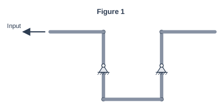
Figure 1 shows a linkage. The input link is pulled to the left.
Which statement describes the movement of the output link?
Choose your answer.
A It moves to the left, parallel to the input link
B It moves to the right, in the opposite direction to the input link
C It moves upwards, at 90° to the input link
D It does not move, because the fixed pivots stop it
Model answer
A It moves to the left, parallel to the input link
Explanation
This is a parallel motion linkage: two levers pivoted at their centres are joined by a connecting link, so both levers turn the same way and the output moves in the same direction as the input, parallel to it. Option B describes a reverse motion linkage, and option C describes a bell crank.
Mark scheme
1 mark
A / It moves to the left, parallel to the input link
Accept the letter or the option text. If more than one option is given, 0 marks.
Question 2
2 marks
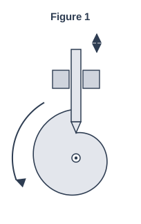
Figure 1 shows a snail (drop) cam with a knife-edge follower.
Explain why this cam can only be turned in one direction.
Model answer
The snail cam rises slowly round almost the whole of its profile and then has a sudden step where the follower drops. If the cam turned the other way, the follower would run into the face of the step and could not climb it, so the cam would jam and the follower could be damaged.
Explanation
The snail cam gives a slow, steady rise and then a sudden drop as the follower falls off the step. That step is also why it must turn one way only: turned backwards, the follower meets a vertical face instead of a slope. One mark is for the step and one for the consequence (jamming).
Mark scheme
1 mark
The cam has a sudden step (drop) in its profile
Accept 'one side of the cam has a sharp step/edge'.
1 mark
If it turned the other way, the follower would hit the step and jam, stopping the cam (or damaging the follower)
Linked consequence. Accept 'the follower could not climb up the step'. Do not accept 'it would not work' alone.
Question 3
3 marks
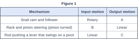
Figure 1 shows three mechanisms with their input and output motions.
Use the words linear, oscillating, reciprocating or rotary to state the type of motion at A, B and C.
Model answer
A: reciprocating B: rotary C: oscillating
Explanation
A cam turns rotary motion into the reciprocating (up and down) motion of the follower. In rack and pinion steering the driver turns the pinion (rotary), which moves the rack sideways (linear). A rod pushing a lever about a pivot converts linear motion into oscillating motion, because the lever swings in an arc.
Mark scheme
1 mark
A: reciprocating
Accept 'up and down in a straight line'. Do not accept linear alone or oscillating.
1 mark
B: rotary
Do not accept turning or circular (the question asks for the named types).
1 mark
C: oscillating
Accept 'swinging in an arc'. Do not accept reciprocating or rotary.
Question 4
6 marks
Use notes to explain how the pistons, connecting rods, crankshaft and camshaft in a four-stroke car engine work together to convert motion and to open and close the valves.
Model answer
1. When the fuel and air mixture burns, the high pressure pushes the piston down the cylinder. This is reciprocating (linear) motion. 2. The piston is joined by a connecting rod to a crank on the crankshaft. The piston, connecting rod and crank form a crank and slider mechanism, which converts the reciprocating motion of the piston into rotary motion of the crankshaft. A heavy flywheel keeps the crankshaft turning through the other three strokes. 3. The crankshaft drives the camshaft through a timing belt or chain. In a four-stroke engine the camshaft turns at half the speed of the crankshaft, because each valve opens once every two turns of the crankshaft. 4. Each cam on the camshaft has a nose (lobe). As the nose comes round, it pushes the follower (tappet), which pushes the valve open. Here the cam converts rotary motion back into reciprocating motion. 5. When the nose has passed, a strong valve spring pushes the valve shut and keeps the follower pressed against the cam. 6. The cams are set at different angles so the inlet valve opens on the intake stroke to let fuel and air in, and the exhaust valve opens on the exhaust stroke to let burnt gases out. Both stay closed during compression and power. 7. The crankshaft and camshaft turn in bearings and are lubricated with oil to reduce friction and wear.
Explanation
A top answer follows the motion through the engine: the piston's reciprocating motion is turned into rotary motion by the connecting rod and crankshaft (a crank and slider), and the crankshaft drives the camshaft, whose cams turn rotary motion back into the reciprocating motion of the valves, with springs closing them. Correct terms (reciprocating, rotary, follower, timing belt) and the right order are needed for Level 3. Listing parts without explaining them is capped at 2 marks.
Mark scheme
6 marks
Levels of response (6 marks). Level 3 (5-6 marks): Detailed explanation including all key stages of how the parts work together, covering the conversion of reciprocating motion to rotary motion and the opening and closing of the valves by the cams, using correct terms. Notes are clear and in a logical order. Level 2 (3-4 marks): Some stages explained in detail OR the majority of stages covered but with insufficient detail to show how the engine works. Level 1 (1-2 marks): One or more basic points or parts listed. 0 marks: No response or nothing worthy of credit.
Max 2 if the parts are only listed with no explanation. Max 4 if the valve operation (cams) is not explained, or if the conversion of motion is not explained. Indicative content (accept all other valid responses): - Burning fuel pushes the piston down the cylinder: reciprocating (linear) motion. - The connecting rod joins the piston to a crank on the crankshaft; together they act as a crank and slider, converting reciprocating motion into rotary motion. - The crankshaft turns; a flywheel keeps it turning through the strokes that do not produce power. - The crankshaft drives the camshaft through a timing belt or chain (in a four-stroke engine the camshaft turns at half the crankshaft speed). - Each cam's nose (lobe) pushes its follower (tappet), which opens a valve: the cam converts rotary motion into reciprocating motion. - A valve spring closes the valve and keeps the follower in contact as the cam's base circle comes round. - The cam shapes and timing make the inlet valve open on the intake stroke and the exhaust valve open on the exhaust stroke. - Bearings support the crankshaft and camshaft, and oil lubricates the moving parts.
Ready to try the rest? Every answer you write is marked against the mark scheme, so you can see exactly where the marks are.
Ctrl + Enter to check
Study HelperHints first, answers after you try
Stuck on this one? Ask for a hint and I’ll point you in the right direction, without giving the answer away. Once you’ve checked your answer, I’ll show you how the marks are awarded.