Practise 15 exam-style questions on Pneumatic and hydraulic systems for AQA GCSE Engineering. Write your answer as you would in the exam and get it marked in seconds against the mark scheme, point by point, with the Study Helper on hand if you get stuck.
15 questions
1–8 marks each
Instant marking
No sign-up needed
15 questions, marked as you go
Sample questions with model answers
Here are 4 of the questions in this topic, each with a model answer, an explanation of why it earns the marks and the mark scheme an examiner would use.
Question 1
1 mark
A pneumatic system works at a pressure of 0.6 N/mm².
Which unit is equal to 1 N/mm²?
Choose your answer.
A 1 Pa
B 1 kPa
C 1 MPa
D 1 GPa
Model answer
C 1 MPa
Explanation
1 Pa is 1 N/m², and 1 m² = 1 000 000 mm², so 1 N/mm² = 1 000 000 N/m² = 1 000 000 Pa = 1 MPa (megapascal). So 0.6 N/mm² is 0.6 MPa.
Mark scheme
1 mark
C / 1 MPa
Accept the letter or the option text. If more than one option is given, 0 marks.
Question 2
2 marks
In a double-acting cylinder, the force produced on the instroke (when the rod moves in) is smaller than the force on the outstroke, even though the air pressure is the same.
Explain why.
Model answer
On the outstroke the air pushes on the whole face of the piston. On the instroke it pushes on the rod side, where the piston rod is attached and takes up part of the area, so the air acts on a smaller ring-shaped area. Since force = pressure × area, the same pressure on a smaller area gives a smaller force.
Explanation
The effective area on the rod side is the piston area minus the area of the rod, so the instroke force is always a little less than the outstroke force. This comes straight from pressure = force ÷ area, rearranged as force = pressure × area. Engineers allow for it when a cylinder must pull a heavy load.
Mark scheme
1 mark
On the instroke the air pushes on the rod side of the piston, where the piston rod takes up part of the area, so the area the air acts on is smaller
Accept 'the rod covers some of the piston'. Do not accept 'the air leaks' or 'the rod is in the way' with no reference to area.
1 mark
Force = pressure × area, so at the same pressure a smaller area gives a smaller force
Accept the relationship in words: 'less area means less force for the same pressure'.
Question 3
4 marks
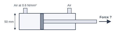
Figure 1 shows a double-acting pneumatic cylinder on a packaging machine. The cylinder has a bore (inside diameter) of 50 mm and is supplied with air at a pressure of 0.6 N/mm².
Calculate the force produced by the cylinder on the outstroke. Give your answer to the nearest newton.
Model answer
r = 50 ÷ 2 = 25 mm A = π × r² = π × 25² = 1963.5 mm² P = F ÷ A, so F = P × A F = 0.6 × 1963.5 = 1178.1 N F = 1178 N (to the nearest newton)
Explanation
Pressure = force ÷ area must be rearranged to force = pressure × area. The area is that of the piston, π × r², using the radius (25 mm), not the diameter. Because the pressure is in N/mm² and the area in mm², the force comes out directly in newtons: 0.6 × 1963.5 = 1178 N. Using the diameter as the radius gives 4712 N, four times too big.
Mark scheme
1 mark
Radius = 50 ÷ 2 = 25 mm; or a correct final answer of 1178 N with no working
An answer of 1178 N with no working scores 4 marks. Accept [1177, 1179] N for the final answer, as π, 3.14 or 3.142 may be used.
1 mark
Area = π × 25² = 1963.5 mm²
Accept [1962.5, 1963.75] mm² (π, 3.14 or 3.142). Allow ECF from a wrong radius: π × 50² = 7854 mm² scores this mark (and leads to 4712 N, which scores 3 marks in total).
1 mark
Pressure = force ÷ area rearranged and substituted: F = P × A = 0.6 × 1963.5
Allow ECF: 0.6 × their area. 0.6 ÷ 1963.5 or 1963.5 ÷ 0.6 does not score this mark or the next.
1 mark
F = 1178 N
Accept [1177, 1179] N, e.g. 1177.5 N (π = 3.14) or 1178.25 N (π = 3.142). Accept 1.18 kN. Allow ECF: 0.6 × their area correctly worked out.
Question 4
6 marks
A drilling machine has a pneumatic clamp that holds the work still. The clamp is a single-acting cylinder controlled by a push-button 3/2 valve. Air is supplied by a compressor.
Use notes to explain how the pneumatic system clamps the work and then releases it, starting from the compressor.
Model answer
1. The compressor draws in air and compresses it. The compressed air is stored in a receiver so there is a steady supply. 2. The air goes through a filter, which removes water and dirt, and a regulator, which sets a safe, constant working pressure (for example 0.6 N/mm²). 3. A pipe carries the air to the 3/2 push-button valve. While the button is up, the valve blocks the supply and connects the cylinder to the exhaust. 4. When the operator presses the button, the valve opens and compressed air flows through the port into the single-acting cylinder. 5. The air pressure acts on the piston, giving a force equal to pressure × piston area. The piston moves out, compressing the return spring, and the rod pushes the clamp pad firmly onto the work. 6. The work is held still while it is drilled. 7. When the button is released, the valve springs back: the supply is shut off and the air in the cylinder escapes through the valve's exhaust port to the atmosphere. 8. The return spring pushes the piston back in, so the clamp lifts off and the work can be removed. Safety: the regulator limits the pressure, the operator keeps fingers away from the clamp pad (a guard or two-hand control can be fitted), eye protection is worn, the pipes are checked for damage, and the air is isolated and released before any maintenance.
Explanation
A Level 3 answer follows the air through the system in order: compressor, receiver, filter and regulator, valve, cylinder, and then back out through the exhaust, explaining what the piston and spring do on each stroke. It also includes sensible safety points. Listing the parts without explaining how the valve sends air in and lets it out, or how the spring returns the piston, stays in Level 1 or 2.
Mark scheme
6 marks
Levels of response (6 marks). Level 3 (5-6 marks): Detailed explanation including all key stages from producing the compressed air to the clamp being applied and released, with the components used (compressor, receiver, regulator, valve, cylinder, spring) and safety. Notes are clear and in a logical order. Level 2 (3-4 marks): Some stages described in detail OR the majority of stages covered but with insufficient detail to explain correct operation of the clamp. Level 1 (1-2 marks): One or more basic steps/stages listed. 0 marks: No response or nothing worthy of credit.
Max 2 if the stages are only listed with no detail. Indicative content (in order; accept all other valid responses): - The compressor draws in air from the atmosphere and compresses it; the compressed air is stored in a receiver (reservoir). - The air passes through a filter and a regulator, which cleans it and sets a safe, constant working pressure. - Pipes carry the air to the 3/2 valve, which is normally closed: it blocks the supply and connects the cylinder to the exhaust. - When the operator presses the button, the valve opens and compressed air flows into the cylinder through its port. - The air pressure acts on the piston (force = pressure × area), pushing it out (outstroke) and compressing the return spring; the rod presses the clamp pad onto the work. - The clamp holds the work while the hole is drilled. - When the button is released, the valve's spring returns it: the supply is blocked and the air in the cylinder is exhausted to the atmosphere through the exhaust port. - The return spring pushes the piston back (instroke), releasing the clamp. - Safety: set the regulator to a safe pressure; keep fingers clear of the clamp (guard, or two-hand control); eye protection because of exhaust air and swarf; check pipes and connections; isolate and release the pressure before maintenance; the drill should only start when the work is clamped.
Ready to try the rest? Every answer you write is marked against the mark scheme, so you can see exactly where the marks are.
Ctrl + Enter to check
Study HelperHints first, answers after you try
Stuck on this one? Ask for a hint and I’ll point you in the right direction, without giving the answer away. Once you’ve checked your answer, I’ll show you how the marks are awarded.