Practise 9 exam-style questions on Standard circuit diagram symbols for AQA GCSE Combined Science (Physics Paper 1). Write your answer as you would in the exam and get it marked in seconds against the mark scheme, point by point, with the Study Helper on hand if you get stuck.
9 questions
1–4 marks each
Instant marking
No sign-up needed
9 questions, marked as you go
Sample questions with model answers
Here are 4 of the questions in this topic, each with a model answer, an explanation of why it earns the marks and the mark scheme an examiner would use.
Question 1
1 mark
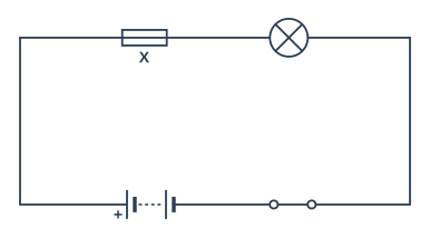
The circuit diagram shows a lamp connected to a battery through a switch and a component labelled X.
Name component X.
Model answer
Component X is a fuse.
Explanation
The fuse symbol is a small rectangle with a line running through it from end to end. A resistor is a plain rectangle with no line through it.
Mark scheme
1 mark
fuse
do not accept resistor
Question 2
2 marks
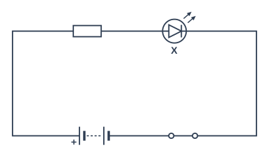
The circuit diagram shows a component labelled X.
Name component X and state what it does when a current flows through it.
Model answer
Component X is a light-emitting diode (LED). It emits light when a current flows through it in the forward direction.
Explanation
The LED symbol is a diode symbol with two small arrows pointing away from it, showing light being given out. Like a diode, it only lets current flow in one direction.
Mark scheme
1 mark
light-emitting diode / LED
do not accept diode alone
1 mark
it emits light
allow it lights up; allow current only flows through it in one direction
Question 3
2 marks
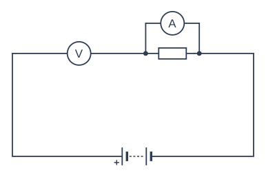
A student wants to measure the current through a resistor and the potential difference across it. The diagram shows the circuit she set up.
Describe what is wrong with the way the meters are connected in her circuit.
Model answer
The voltmeter has been connected in series with the resistor, but it should be connected in parallel across the resistor. The ammeter has been connected in parallel with the resistor, but it should be connected in series with it.
Explanation
An ammeter measures the current through a component, so it goes in series (in the same loop). A voltmeter measures the potential difference across a component, so it is connected in parallel, across that component.
Mark scheme
1 mark
the voltmeter is connected in series but should be in parallel with (across) the resistor
1 mark
the ammeter is connected in parallel with the resistor but should be in series with it
allow the meters are the wrong way round / have been swapped for 1 mark only if neither connection is described
Question 4
3 marks
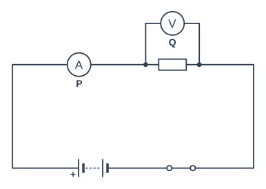
The circuit diagram shows two meters, P and Q. Meter Q is a voltmeter.
Name meter P and state what it measures. Explain why the voltmeter Q is connected in parallel with the resistor.
Model answer
P is an ammeter. It measures the current through the resistor, which is the same as the current at every point in this single loop. A voltmeter measures the potential difference across a component, which is the difference between the two ends of it, so it has to be connected in parallel with the resistor.
Explanation
Both meters are drawn as circles containing a letter: A for an ammeter and V for a voltmeter. An ammeter goes in series to measure the current through a component; a voltmeter goes in parallel to compare the two ends of the component.
Mark scheme
1 mark
P is an ammeter
1 mark
it measures the current (through the resistor / in the circuit)
1 mark
a voltmeter measures the potential difference across a component, so it must be connected across (in parallel with) it
allow it measures the difference in potential between the two ends of the resistor
Ready to try the rest? Every answer you write is marked against the mark scheme, so you can see exactly where the marks are.
Ctrl + Enter to check
Study HelperHints first, answers after you try
Stuck on this one? Ask for a hint and I’ll point you in the right direction, without giving the answer away. Once you’ve checked your answer, I’ll show you how the marks are awarded.