Level:
Correct: 0
Incorrect: 0
Marks: 0/0
Exam Practice
Course:
Topics:
Avg
score:
–
Topics
done:
0/30

Current, resistance and potential difference

Practise 15 exam-style questions on Current, resistance and potential difference for AQA GCSE Combined Science (Physics Paper 1). Write your answer as you would in the exam and get it marked in seconds against the mark scheme, point by point, with the Study Helper on hand if you get stuck.

  • 15 questions
  • 1–6 marks each
  • Instant marking
  • No sign-up needed
15 questions, marked as you go

Sample questions with model answers

Here are 4 of the questions in this topic, each with a model answer, an explanation of why it earns the marks and the mark scheme an examiner would use.

Question 1

2 marks

The current in a 12 Ω resistor is 0.50 A.

Calculate the potential difference across the resistor.

Model answer

V = I R
V = 0.50 × 12
V = 6.0 V

Explanation

Potential difference = current × resistance. With current in amperes and resistance in ohms, the answer is in volts.

Mark scheme
  1. 1 mark

    V = 0.50 × 12

    an answer of 6.0 (V) scores 2 marks

  2. 1 mark

    6.0 (V)

    allow 6 (V)

Question 2

2 marks

In an investigation into how the resistance of a wire depends on its length, the student switches off the circuit between readings.

Explain why.

Model answer

When a current flows in the wire it heats up. A hotter wire has a greater resistance, so if the wire were left switched on, the resistance would change because of the temperature as well as the length. Switching off keeps the temperature constant, so it is a fair test.

Explanation

The investigation is only valid if length is the only variable changing. Temperature also affects resistance, so it must be controlled by keeping the current small and on for as short a time as possible.

Mark scheme
  1. 1 mark

    the current heats the wire / the temperature of the wire would increase

  2. 1 mark

    the resistance increases as the temperature increases, so temperature must be kept constant for a fair test

    allow temperature is a control variable

Question 3

3 marks

A student plotted a graph of resistance against length for a wire. His line of best fit was straight but it crossed the resistance axis at 0.3 Ω instead of passing through the origin.

Suggest a reason for this, and describe how it affects his results.

Model answer

The crocodile clips and the contacts between them and the wire have some resistance, which is measured as well as the resistance of the wire. This is a systematic (zero) error: it adds about 0.3 Ω to every resistance value, so the line is shifted up but has the same gradient.

Explanation

A systematic error shifts every reading by the same amount, so a graph that should pass through the origin has an intercept instead. It does not change the gradient, so the conclusion that resistance increases steadily with length is still valid.

Mark scheme
  1. 1 mark

    the crocodile clips / connecting leads have some resistance

    allow the zero of the metre rule was not lined up with the fixed clip; allow a zero error on the meters

  2. 1 mark

    this is a systematic error / zero error

  3. 1 mark

    it adds the same amount (0.3 Ω) to every resistance value

    allow correct by subtracting 0.3 Ω from each reading

Question 4

4 marks

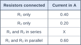
A student measured the current through two resistors, R₁ and R₂, on their own and in combination, using the same 6.0 V supply each time. The table shows her results.

Calculate the resistance of R₁ and of R₂, and then predict the value of X.
Give X to 2 significant figures.

Table with columns "Resistors connected", "Current in A". Resistors connected: R₁ only; Current in A: 0.40 | Resistors connected: R₂ only; Current in A: 0.20 | Resistors connected: R₁ and R₂ in series; Current in A: X | Resistors connected: R₁ and R₂ in parallel; Current in A: 0.60.

Model answer

R₁ = V ÷ I = 6.0 ÷ 0.40 = 15 Ω
R₂ = V ÷ I = 6.0 ÷ 0.20 = 30 Ω
In series, total resistance = 15 + 30 = 45 Ω
X = 6.0 ÷ 45 = 0.133... A = 0.13 A (2 s.f.)

Explanation

In series, the resistances add, so the total resistance is bigger than either resistor and the current is smaller than in either alone. In parallel, the currents in the two branches add (0.40 + 0.20 = 0.60 A), which is why the parallel combination has a smaller resistance than either resistor.

Mark scheme
  1. 1 mark

    R₁ = 6.0 ÷ 0.40 = 15 (Ω)

    an answer of 0.13 (A) scores 4 marks

  2. 1 mark

    R₂ = 6.0 ÷ 0.20 = 30 (Ω)

  3. 1 mark

    total resistance in series = 15 + 30 = 45 (Ω)

    allow ecf from their resistances

  4. 1 mark

    X = 6.0 ÷ 45 = 0.13 (A)

    allow ecf for their value given to 2 significant figures; an answer of 0.60 (A) (adding currents) scores 2 marks

Ready to try the rest? Every answer you write is marked against the mark scheme, so you can see exactly where the marks are.

Revision notes

Current, resistance and potential difference

The big idea

The current through a component depends on two things: the potential difference across it, which drives the charge, and its resistance, which opposes the flow. One equation, \(V = IR\), links all three, and you will use it in almost every electricity topic. You also need to know how to investigate what affects resistance.

Current, potential difference and resistance

  • A bigger potential difference (p.d.) across a component makes a bigger current flow through it.
  • The greater the resistance of a component, the smaller the current for a given potential difference.

Exam questions say "potential difference", but you can also write "voltage" and still get the marks. Potential difference is measured with a voltmeter connected in parallel across the component; current is measured with an ammeter in series with it.

\[\text{potential difference} = \text{current} \times \text{resistance} \qquad V = IR\]
  • potential difference, \(V\), in volts, V
  • current, \(I\), in amperes, A (amp is also fine)
  • resistance, \(R\), in ohms, Ω

You must recall this equation. Rearranged, \(I = \dfrac{V}{R}\) and \(R = \dfrac{V}{I}\). Resistance cannot be read off a meter in this circuit: you measure \(V\) and \(I\) and calculate \(R\).

Watch the prefixes: 1 kΩ = 1000 Ω and 1 mA = 0.001 A.

Testing soil with a moisture probe

A gardener's moisture probe puts a potential difference of 3.0 V across two metal prongs pushed into the soil. The current through the soil is 1.5 mA. Calculate the resistance of the soil between the prongs in kilohms.

\(I = 1.5 \div 1000 = 0.0015\) A

\(V = IR\), so \(R = \dfrac{V}{I} = \dfrac{3.0}{0.0015} = 2000\ \Omega\)

\(2000 \div 1000 = 2.0\) kΩ

Heated gloves

Each glove of a pair of heated gloves contains a heating wire with a resistance of 2.4 Ω. It is connected to a 3.7 V battery. Calculate the current in the wire.

\(V = IR\), so \(I = \dfrac{V}{R} = \dfrac{3.7}{2.4} = 1.541\ldots\)

\(I = 1.5\) A (2 significant figures)

What affects the resistance of a wire

  • Length: at constant temperature, the resistance is directly proportional to the length. Doubling the length doubles the resistance, because the charge has to pass through twice as much wire.
  • Temperature: the resistance of a metal wire increases as it gets hotter. A current heats a wire, so in experiments keep the current small and switch off between readings.
  • Thickness and material also matter, so keep them the same when you investigate length.

Joining resistors also changes the total resistance: in series the total is bigger than either resistor, and in parallel it is smaller than the smallest one (see also: Series and parallel circuits).

Required practical: Resistance of a wire and of resistor combinations

Tape a length of resistance wire along a metre rule. Connect it in series with a power supply and an ammeter, and connect a voltmeter across the length of wire between a fixed crocodile clip at 0 cm and a movable clip.

Diagram of the apparatus for investigating how the resistance of a wire depends on its length. A wire is taped along a metre rule. One crocodile clip is fixed at the zero end and a second, movable crocodile clip is on the wire further along; the length between them is marked l. The clips are connected to a power supply with an ammeter in series, and a voltmeter is connected across the length of wire between the clips. Labelled parts: Ammeter, Voltmeter, Resistance wire, Power supply, Crocodile clip, Metre rule. (the movable clip is at the 70 cm mark.)
The voltmeter measures the potential difference across the length of wire l between the clips.
  • Set the movable clip at a length such as 10 cm, switch on, record the current and potential difference, then switch off. Repeat at least every 10 cm up to 100 cm.
  • Calculate \(R = \dfrac{V}{I}\) for each length and plot a graph of resistance (y-axis) against length (x-axis).
  • Independent variable: length. Dependent variable: resistance. Control variables: the wire's material, thickness and temperature.
  • Use a low potential difference and switch off between readings, so the wire does not heat up and change its resistance. The wire can still get hot: do not touch it while the current is on.
  • Typical result: a straight line through the origin, so resistance is directly proportional to length. If the line crosses the resistance axis above zero, there is a systematic error, for example the resistance of the clips and contacts being added to every reading.
  • Combinations: measure \(V\) and \(I\) for one resistor, then for two identical resistors in series, then for the two in parallel, with the voltmeter across the whole combination and the ammeter measuring the total current. Series gives the largest resistance and parallel the smallest.

Common mistakes

  • Working out \(I \div V\) instead of \(V \div I\) for the resistance. Write \(V = IR\) first, then rearrange.
  • Using milliamps or kilohms without converting to amps and ohms.
  • Concluding only that "resistance increases with length" from a straight line through the origin. Say it is directly proportional.
  • Leaving the circuit switched on throughout the practical. The wire heats up and its resistance rises.
  • Connecting the voltmeter in series with the wire. It goes across the length being tested.

Exam tip

In 6-mark practical questions, name the meters and where they go, say what you change and over what range, how you keep the temperature constant, and how you use the results (calculate \(R = V \div I\) and plot a graph). In calculations, an answer with no unit can lose a mark when the question asks for it.

Study Helper Hints first, answers after you try

Stuck on this one? Ask for a hint and I’ll point you in the right direction, without giving the answer away. Once you’ve checked your answer, I’ll show you how the marks are awarded.