Level:
Correct: 0
Incorrect: 0
Marks: 0/0
Exam Practice
Course:
Topics:
Avg
score:
–
Topics
done:
0/30

Resistors

Practise 18 exam-style questions on Resistors for AQA GCSE Combined Science (Physics Paper 1). Write your answer as you would in the exam and get it marked in seconds against the mark scheme, point by point, with the Study Helper on hand if you get stuck.

  • 18 questions
  • 1–6 marks each
  • Instant marking
  • No sign-up needed
18 questions, marked as you go

Sample questions with model answers

Here are 4 of the questions in this topic, each with a model answer, an explanation of why it earns the marks and the mark scheme an examiner would use.

Question 1

2 marks

Explain why the resistance of a filament lamp increases as the current through it increases.

Model answer

As the current increases, more energy is transferred to the filament each second, so its temperature increases. The resistance of the filament increases as its temperature increases.

Explanation

A filament lamp is not an ohmic conductor because its temperature does not stay constant. The hotter the filament, the higher its resistance, which is why its I–V graph curves and gets less steep at higher potential differences.

Mark scheme
  1. 1 mark

    a larger current makes the filament hotter / increases its temperature

  2. 1 mark

    the resistance of the filament increases as its temperature increases

    allow the ions in the filament vibrate more, so electrons collide with them more often

Question 2

2 marks

A student measured the current through a length of thin wire for different potential differences. Her I–V graph was a straight line through the origin at low potential differences, but curved and became less steep at high potential differences.

Suggest why.

Model answer

At high potential differences the current is large enough to heat the thin wire, so its temperature increases. The resistance of the wire increases as it gets hotter, so the current increases less than in proportion to the potential difference and the graph curves.

Explanation

A wire is an ohmic conductor only at constant temperature. Once it starts to heat up it behaves like a filament lamp, with a resistance that increases as the current increases.

Mark scheme
  1. 1 mark

    at high potential differences the current is large enough to heat the wire / the temperature of the wire increases

  2. 1 mark

    the resistance of the wire increases as it gets hotter, so the current is no longer proportional to the potential difference

    allow the wire is only ohmic at constant temperature

Question 3

3 marks

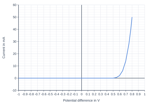
The graph shows the current–potential difference (I–V) characteristic of a diode.

Use the graph to describe how the current through the diode depends on the potential difference across it.

Line graph of current in mA (y-axis, -10 to 60) against Potential difference in V (x-axis, -1 to 1). The line joins the points (-1, 0), (0.5, 0), (0.55, 0.5), (0.6, 2), (0.65, 6), (0.7, 14), (0.75, 28), (0.78, 40), (0.8, 50).

Model answer

When the potential difference is negative (the reverse direction), the current is zero, because the diode has a very high resistance in the reverse direction. In the forward direction there is still no current until the potential difference reaches about 0.5-0.6 V. Above this the current increases very rapidly, reaching 50 mA at 0.8 V.

Explanation

A diode lets current flow in one direction only. Its graph is non-linear: even in the forward direction it needs a small potential difference before it conducts, after which its resistance becomes very low.

Mark scheme
  1. 1 mark

    when the potential difference is negative (reverse direction) the current is zero

  2. 1 mark

    because the diode has a very high resistance in the reverse direction

    allow current only flows in one direction

  3. 1 mark

    in the forward direction there is no current until about 0.5-0.6 V, then the current increases rapidly

    allow the current increases steeply above about 0.6 V; allow any value 0.5-0.6 V

Question 4

4 marks

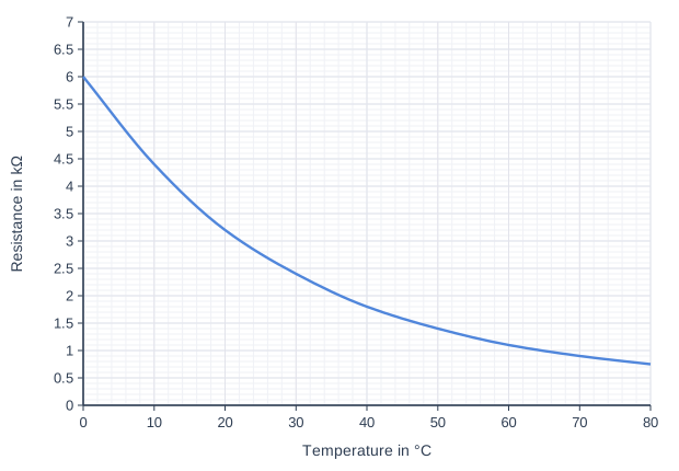
The graph shows how the resistance of a thermistor changes with temperature. The thermistor is connected on its own to a 6.0 V battery.

Use the graph to calculate the current in the thermistor when its temperature is 30 °C.
Give your answer in milliamps.

Line graph of resistance in kΩ (y-axis, 0 to 7) against temperature in °C (x-axis, 0 to 80). The line is a smooth curve through (0, 6), (10, 4.4), (20, 3.2), (30, 2.4), (40, 1.8), (50, 1.4), (60, 1.1), (70, 0.9), (80, 0.75).

Model answer

From the graph, the resistance at 30 °C is 2.4 kΩ = 2400 Ω.
V = I R
6.0 = I × 2400
I = 6.0 ÷ 2400 = 0.0025 A
I = 2.5 mA

Explanation

Read the resistance at 30 °C from the curve, convert kilohms to ohms, then use I = V ÷ R. Multiply amperes by 1000 to give milliamps. At higher temperatures the resistance is lower, so the current would be larger.

Mark scheme
  1. 1 mark

    resistance at 30 °C = 2.4 kΩ = 2400 Ω

    an answer of 2.5 (mA) scores 4 marks; allow 2.3-2.5 kΩ

  2. 1 mark

    6.0 = I × 2400

    allow I = 6.0 ÷ 2400; allow ecf from their reading

  3. 1 mark

    I = 0.0025 (A)

    allow ecf

  4. 1 mark

    2.5 (mA)

    allow 2.4-2.6 (mA); allow ecf from their current in A × 1000

Ready to try the rest? Every answer you write is marked against the mark scheme, so you can see exactly where the marks are.

Revision notes

Resistors

The big idea

For some components the resistance stays the same whatever the current; for others it changes as the current changes. A graph of current against potential difference, called an I–V characteristic, shows which kind a component is. Components whose resistance changes are useful: thermistors and LDRs let circuits respond to temperature and light.

Ohmic conductors

The current through an ohmic conductor (at constant temperature) is directly proportional to the potential difference across it, so its resistance stays constant as the current changes. A fixed resistor at constant temperature and a metal wire kept cool are ohmic.

To decide whether a component is ohmic, plot current against potential difference: a straight line through the origin means it is ohmic. Or calculate \(R = \dfrac{V}{I}\) for each pair of readings: if every value is the same, it is ohmic.

Is the component ohmic?

A student measures the current through a component at three potential differences.

Potential difference in VCurrent in A
1.00.050
2.00.100
4.00.160

Is the component ohmic over this range? Use \(R = \dfrac{V}{I}\) for each row:

\(\dfrac{1.0}{0.050} = 20\ \Omega\), \(\dfrac{2.0}{0.100} = 20\ \Omega\), \(\dfrac{4.0}{0.160} = 25\ \Omega\)

The resistance is constant at first but rises at 4.0 V, so the component is not ohmic over the whole range. It behaves like a filament lamp: the larger current heats it.

I–V characteristics

Line graph of Current in A (y-axis, -0.4 to 0.4) against Potential difference in V (x-axis, -6 to 6). "Resistor" joins the points (-6, -0.2), (6, 0.2). "Filament lamp" (dashed) is a smooth curve through (-6, -0.33), (-5, -0.31), (-4, -0.29), (-3, -0.26), (-2, -0.21), (-1, -0.13), (-0.5, -0.07), (0, 0), (0.5, 0.07), (1, 0.13), (2, 0.21), (3, 0.26), (4, 0.29), (5, 0.31), (6, 0.33). "Diode" joins the points (-6, 0), (0.5, 0), (0.6, 0.02), (0.7, 0.1), (0.75, 0.2), (0.8, 0.38).
Negative potential differences mean the component is connected the other way round.
  • Resistor at constant temperature: a straight line through the origin, the same shape in both directions. Linear, so the resistance is constant.
  • Filament lamp: a curve that gets less steep as the potential difference rises, the same shape in both directions. The current keeps increasing, but by less for each extra volt. A bigger current makes the filament hotter; the metal ions vibrate more, so electrons collide with them more often and the resistance increases.
  • Diode: the current flows in one direction only. In the reverse direction the diode has a very high resistance, so almost no current flows. In the forward direction there is almost no current until about 0.6 V; then the current rises very steeply.

The resistance at any point is \(R = \dfrac{V}{I}\) using that point's values read from the graph, not the gradient of the curve.

Thermistors and LDRs

  • The resistance of a thermistor decreases as the temperature increases.
  • The resistance of a light-dependent resistor (LDR) decreases as the light intensity increases.

They turn a change in the surroundings into a change in resistance, and so into a change in current or potential difference that can work a switch.

  • Thermostat: as a room warms up, the thermistor's resistance falls, so the current in its circuit rises. At a set current the circuit switches the heater off. A fridge uses the same idea to switch its cooling on.
  • Lights that switch on when it gets dark: an LDR is in series with a fixed resistor. As it gets dark, the LDR's resistance rises, so it takes a bigger share of the supply's potential difference. When the potential difference across the LDR passes a set value, the lamp switches on.

Required practical: I–V characteristics

Connect the component in series with an ammeter, a variable resistor, a switch and a battery, with a voltmeter across the component. (The same circuit measures the resistance of any component: \(R = V \div I\).)

Circuit diagram. Going round the loop from the + terminal of the battery, in the direction conventional current flows: an ammeter; then a lamp labelled "filament lamp", with a voltmeter connected across it; then a variable resistor (labelled "variable resistor"); then a closed switch; and back to the − terminal of the battery.
Swap the lamp for a resistor, or for a diode with a protective resistor in series.
  • Adjust the variable resistor to change the potential difference across the component; record the current and potential difference for at least six values.
  • Reverse the connections to the component and repeat to get negative values.
  • Repeat the readings, calculate means and plot current (y-axis) against potential difference (x-axis).
  • For a diode, add a resistor in series to limit the current, because the current rises steeply once it conducts.
  • For the resistor, switch off between readings so its temperature stays constant.
  • Safety: the lamp gets hot, so do not touch it, and do not go above its rated potential difference.

Common mistakes

  • Saying a thermistor's resistance increases with temperature. It decreases: that is the opposite of a filament lamp.
  • Saying the current through a lamp decreases at high potential difference. It still increases, just more slowly.
  • Finding resistance from 1 ÷ the gradient of a curve. Use \(V \div I\) at the point.
  • Calling a component ohmic because its graph is a straight line. It must also pass through the origin.
  • Explaining a lamp's curve without temperature. The resistance rises because the filament gets hotter.

Exam tip

For "explain the shape" questions, link each feature of the graph to the physics in a chain: bigger current, hotter filament, more collisions, higher resistance, curve flattens. When asked to compare two I–V graphs, describe both components, not just one.

Study Helper Hints first, answers after you try

Stuck on this one? Ask for a hint and I’ll point you in the right direction, without giving the answer away. Once you’ve checked your answer, I’ll show you how the marks are awarded.