Level:
Correct: 0
Incorrect: 0
Marks: 0/0
Exam Practice
Course:
Topics:
Avg
score:
–
Topics
done:
0/30

Series and parallel circuits

Practise 18 exam-style questions on Series and parallel circuits for AQA GCSE Combined Science (Physics Paper 1). Write your answer as you would in the exam and get it marked in seconds against the mark scheme, point by point, with the Study Helper on hand if you get stuck.

  • 18 questions
  • 1–6 marks each
  • Instant marking
  • No sign-up needed
18 questions, marked as you go

Sample questions with model answers

Here are 4 of the questions in this topic, each with a model answer, an explanation of why it earns the marks and the mark scheme an examiner would use.

Question 1

2 marks

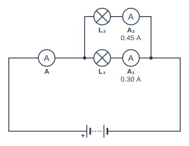
The circuit diagram shows two lamps, L₁ and L₂, connected in parallel. Ammeter A₁ reads 0.30 A and ammeter A₂ reads 0.45 A.

What is the reading on ammeter A? Give a reason for your answer.

Circuit diagram. Going round the loop from the + terminal of the battery: ammeter A; then two branches in parallel (one branch has lamp L₁ then ammeter A₁ (reading 0.30 A); the other branch has lamp L₂ then ammeter A₂ (reading 0.45 A)); and back to the − terminal of the battery.

Model answer

Ammeter A reads 0.75 A. In a parallel circuit, the total current through the whole circuit is the sum of the currents through the separate branches: 0.30 + 0.45 = 0.75 A.

Explanation

Charge splits at a junction and joins up again, but none is lost. So the current in the main part of the circuit equals the total of the branch currents.

Mark scheme
  1. 1 mark

    0.75 (A)

  2. 1 mark

    the total current is the sum of the currents through the separate branches / 0.30 + 0.45

Question 2

2 marks

A string of decorative lights has 20 identical lamps connected in series. It is plugged into the 230 V mains supply.

Calculate the potential difference across each lamp.

Model answer

The 230 V is shared equally between 20 identical lamps in series.
Potential difference across each lamp = 230 ÷ 20 = 11.5 V

Explanation

In series, the total potential difference of the supply is shared between the components; identical lamps have equal resistances, so they get equal shares. This is why each lamp in such a string is designed for a low potential difference.

Mark scheme
  1. 1 mark

    230 ÷ 20

    an answer of 11.5 (V) scores 2 marks; the supply potential difference is shared equally between identical lamps in series

  2. 1 mark

    11.5 (V)

    allow 12 (V)

Question 3

3 marks

A lamp works at normal brightness when the potential difference across it is 3.5 V and the current through it is 0.30 A. A student wants to run the lamp at normal brightness from a 6.0 V battery by connecting a resistor in series with it.

Calculate the resistance of the resistor needed.
Give your answer to 2 significant figures.

Model answer

Potential difference across resistor = 6.0 − 3.5 = 2.5 V
Current through resistor = current through lamp = 0.30 A
R = V ÷ I = 2.5 ÷ 0.30 = 8.33... Ω
R = 8.3 Ω (2 s.f.)

Explanation

The resistor must take the 'extra' potential difference that the lamp does not need, and in series it carries the same current as the lamp. This is an example of designing a series circuit so a component gets exactly the potential difference it needs.

Mark scheme
  1. 1 mark

    potential difference across resistor = 6.0 − 3.5 = 2.5 (V)

    an answer of 8.3 (Ω) scores 3 marks

  2. 1 mark

    R = 2.5 ÷ 0.30 = 8.33...

    current in resistor is 0.30 A (same as lamp); allow ecf

  3. 1 mark

    8.3 (Ω)

    allow ecf for their value given to 2 significant figures; an answer of 20 (Ω) (6.0 ÷ 0.30) scores 1 mark

Question 4

4 marks

A resistor R₁ of resistance 18 Ω is connected in series with an unknown resistor R₂ and a 12 V battery. The current in the circuit is 0.40 A.

Calculate the potential difference across R₂.

Model answer

Total resistance = V ÷ I = 12 ÷ 0.40 = 30 Ω
R₂ = 30 − 18 = 12 Ω
Potential difference across R₂ = I × R₂ = 0.40 × 12 = 4.8 V
(Check: potential difference across R₁ = 0.40 × 18 = 7.2 V, and 7.2 + 4.8 = 12 V)

Explanation

Treat the two resistors as one equivalent resistance to find the total, then subtract the known resistor. Alternatively, find the potential difference across R₁ and subtract it from the supply, since potential differences in series add up to the supply potential difference.

Mark scheme
  1. 1 mark

    total resistance = 12 ÷ 0.40 = 30 (Ω)

    an answer of 4.8 (V) scores 4 marks; alternative method: potential difference across R₁ = 0.40 × 18 = 7.2 V (2 marks), then 12 − 7.2 = 4.8 V (2 marks)

  2. 1 mark

    R₂ = 30 − 18 = 12 (Ω)

    allow ecf

  3. 1 mark

    V = 0.40 × 12

    allow ecf from their R₂

  4. 1 mark

    4.8 (V)

    allow ecf

Ready to try the rest? Every answer you write is marked against the mark scheme, so you can see exactly where the marks are.

Revision notes

Series and parallel circuits

The big idea

Components can be joined in two ways: in series, one after another in a single loop, or in parallel, on separate branches. The current, the potential difference and the total resistance follow different rules in each, and many circuits have both series and parallel parts. Know the rules and you can work out every meter reading.

The rules

SeriesParallel
Paths for the currentOne loopA separate branch for each component
CurrentThe same through each componentThe total current is the sum of the branch currents
Potential differenceThe supply's p.d. is shared between the componentsThe p.d. across each branch is the same
Total resistanceThe sum of the resistancesLess than the smallest resistance
If one lamp breaksEvery lamp goes outThe other branches keep working

For two resistors in series:

\[R_{\text{total}} = R_1 + R_2\]
  • resistance, \(R\), in ohms, Ω

This rule is not on the equation sheet, so learn it. It works for any number of resistors in series. You never have to calculate the total resistance of resistors in parallel.

In series, the p.d. is shared in the same ratio as the resistances: the larger resistor gets the larger share, because the same current flows through both (\(V = IR\)).

Circuit diagram. Going round the loop from the + terminal of the battery (labelled 6.0 V), in the direction conventional current flows: ammeter A₁ (reading 0.75 A); then two branches in parallel (one branch has lamp L then ammeter A₂ (reading 0.50 A); the other branch has resistor R then ammeter A₃ (reading 0.25 A)), with voltmeter V (reading 6.0 V) connected across this parallel section; then a closed switch; and back to the − terminal of the battery.
Each branch has the full 6.0 V across it, and the branch currents add up to the current from the battery.

Why the total resistance changes

  • Adding a resistor in series makes the charge pass through one more resistor in turn. The supply's p.d. is shared between more resistors, so for the same supply the current is smaller: the total resistance has increased.
  • Adding a resistor in parallel gives the charge an extra path. The new branch has the full supply p.d. across it and carries extra current, so the total current from the same supply is larger: the total resistance has decreased.

Calculating in series circuits

Replace series resistors with one equivalent resistance (their sum), find the current from the supply's p.d., then use \(V = IR\) for each component.

Making up a resistance

A technician needs a total resistance of at least 50 Ω, but she only has 22 Ω resistors. She joins them in series to a 6.0 V battery. How many resistors does she need, and what current flows?

In series the resistances add. Two give \(22 + 22 = 44\ \Omega\), which is too small, so she needs three: \(R_{\text{total}} = 22 + 22 + 22 = 66\ \Omega\)

\(I = \dfrac{V}{R_{\text{total}}} = \dfrac{6.0}{66} = 0.0909\ldots\), so \(I = 0.091\) A (2 significant figures), the same through each resistor

Each resistor has \(V = IR = 0.0909 \times 22 = 2.0\) V across it, and the three p.d.s add up to the supply's 6.0 V.

A car's electrical system

A car's two headlamps, each with a resistance of 2.4 Ω, are connected in parallel to its 12 V battery. The driver then switches on a heated seat with a resistance of 4.0 Ω, on another parallel branch. Show that switching on the seat decreases the total resistance of the circuit.

Each branch has the full 12 V across it, so each headlamp takes \(I = \dfrac{V}{R} = \dfrac{12}{2.4} = 5.0\) A

Headlamps only: total current \(= 5.0 + 5.0 = 10\) A, so the total resistance is \(\dfrac{12}{10} = 1.2\ \Omega\)

The seat takes \(\dfrac{12}{4.0} = 3.0\) A, so the total current rises to 13 A and the total resistance falls to \(\dfrac{12}{13} = 0.92\ \Omega\) (2 significant figures)

The new branch gives the charge an extra path, so more current flows from the same p.d.: the total resistance has decreased.

Series circuits for measuring and testing

  • To measure a component's resistance, put an ammeter in series with it and a voltmeter across it, then use \(R = V \div I\). An ammeter has a very low resistance so it hardly changes the current; a voltmeter has a very high resistance so it takes almost no current.
  • A continuity tester is a battery, a lamp (or buzzer) and two probes in series. Touch the probes to each end of a fuse or a wire: if the lamp lights, the loop is complete; if not, there is a break.
  • Sensor circuits put a thermistor or an LDR in series with a fixed resistor. When the sensor's resistance changes, the share of the supply p.d. across each part changes (see also: Resistors).

Common mistakes

  • Splitting the supply p.d. between parallel branches. In parallel, each branch has the full supply p.d.
  • Adding resistances that are in parallel. Adding only works for series; in parallel the total is less than the smallest.
  • Saying the current is the same in each branch of a parallel circuit. It only splits equally if the branches are identical.
  • Adding kilohms to ohms without converting: 2.2 kΩ is 2200 Ω.
  • Using one resistor's value with the supply p.d. in a series circuit. Use the total resistance to find the current.

Exam tip

In "explain what happens to the brightness" questions, work through the chain in order: total resistance, then current, then the p.d. across each component, then brightness. In calculations, label each current and p.d. with the component it belongs to, then check: the p.d.s round a series loop add up to the supply p.d., and the branch currents add up to the total current.

Study Helper Hints first, answers after you try

Stuck on this one? Ask for a hint and I’ll point you in the right direction, without giving the answer away. Once you’ve checked your answer, I’ll show you how the marks are awarded.