Level:
Correct: 0
Incorrect: 0
Marks: 0/0
Exam Practice
Course:
Topics:
Avg
score:
–
Topics
done:
0/31

Electric motors (HT only)

Practise 10 exam-style questions on Electric motors (HT only) for AQA GCSE Combined Science (Physics Paper 2). Write your answer as you would in the exam and get it marked in seconds against the mark scheme, point by point, with the Study Helper on hand if you get stuck.

  • 10 questions
  • 1–6 marks each
  • Instant marking
  • No sign-up needed
10 questions, marked as you go

Sample questions with model answers

Here are 4 of the questions in this topic, each with a model answer, an explanation of why it earns the marks and the mark scheme an examiner would use.

Question 1

1 mark

Name the rule used to work out the direction of the force on each side of the coil in an electric motor.

Model answer

Fleming's left-hand rule.

Explanation

Fleming's left-hand rule relates the directions of the field (first finger), the current (second finger) and the force (thumb). Applying it to each side of the coil shows that the forces are in opposite directions, so the coil rotates.

Mark scheme
  1. 1 mark

    Fleming's left-hand rule

    do not accept right-hand rule

Question 2

2 marks

Give two ways of reversing the direction of rotation of a simple d.c. electric motor.

Model answer

Reverse the current by swapping the connections to the power supply. Reverse the magnetic field by swapping the magnet's poles.

Explanation

Reversing either the current or the field reverses the forces on both sides of the coil, so the coil turns the other way. Reversing both at the same time leaves the direction unchanged.

Mark scheme
  1. 1 mark

    reverse the direction of the current

    allow swap the connections to the battery / power supply

  2. 1 mark

    reverse the direction of the magnetic field

    allow swap the poles of the magnet; reversing both together scores 0 for that way

Question 3

3 marks

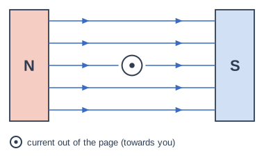
The diagram shows one side of the coil of an electric motor, seen end-on, between the poles of a magnet. The current in this side of the coil is out of the page.

Determine the direction of the force on this side of the coil. Then describe the force on the opposite side of the coil, where the current is into the page, and explain the effect on the coil.

A wire is placed between the N pole (left) and the S pole (right) of a magnet; straight field lines go from N to S (to the right). The wire is seen end-on, with a dot: current out of the page (towards you).

Model answer

Using Fleming's left-hand rule, with the first finger pointing right (field from N to S) and the second finger out of the page (current), the thumb points up, so the force on this side is upwards. On the opposite side the current is into the page, so the force is downwards. One side is pushed up and the other pushed down, so the coil rotates.

Explanation

Because the current flows in opposite directions along the two sides of the coil, the forces on them are also in opposite directions. This pair of forces turns the coil.

Mark scheme
  1. 1 mark

    the force on this side is upwards (towards the top of the diagram)

  2. 1 mark

    the force on the opposite side is downwards

    allow in the opposite direction

  3. 1 mark

    the two forces in opposite directions on opposite sides make the coil rotate

Question 4

4 marks

The coil of an electric motor has 50 turns of wire. On one side of the coil, each of the 50 wires has a length of 4.0 cm at right angles to a magnetic field of magnetic flux density 0.20 T. The current in the wire is 1.5 A.

The equation linking force, magnetic flux density, current and length is:
force = magnetic flux density × current × length

Calculate the total force on this side of the coil.

Model answer

l = 4.0 cm = 0.040 m
Force on one wire: F = B × I × l = 0.20 × 1.5 × 0.040 = 0.012 N
There are 50 wires on this side, each with the same force in the same direction.
Total force = 50 × 0.012 = 0.60 N

Explanation

Every turn of the coil carries the same current through the field, so the forces on all 50 wires add up. This is why motor coils have many turns: more turns give a bigger force and a more powerful motor.

Mark scheme
  1. 1 mark

    4.0 cm = 0.040 m

    an answer of 0.60 (N) scores 4 marks

  2. 1 mark

    force on one wire = 0.20 × 1.5 × 0.040 = 0.012 (N)

    allow ecf from an incorrect conversion

  3. 1 mark

    total force = 50 × 0.012

    allow total length = 50 × 0.040 = 2.0 m and F = 0.20 × 1.5 × 2.0

  4. 1 mark

    total force = 0.60 (N)

    allow ecf; an answer of 0.012 N scores 2 marks; 60 N scores 3 marks (length not converted)

Ready to try the rest? Every answer you write is marked against the mark scheme, so you can see exactly where the marks are.

Revision notes

Electric motors (HT only)

The big idea

A coil of wire carrying a current in a magnetic field tends to rotate. This is the basis of an electric motor. The motor effect pushes the two sides of the coil in opposite directions, and a split-ring commutator keeps the coil turning the same way.

How a simple d.c. motor works

A rectangular coil on an axle sits between the poles of a magnet. The current reaches it through two brushes that press on a split-ring commutator.

  1. The current flows along one side of the coil and back along the other, so the currents in the two sides are in opposite directions.
  2. Each side carries a current at right angles to the magnetic field, so there is a force on each side (the motor effect).
  3. By Fleming's left-hand rule, the forces on the two sides are in opposite directions: one side is pushed up and the other down.
  4. The two forces produce a moment (turning effect) about the axle, so the coil rotates.
  5. Every half turn, the commutator reverses the current in the coil. This reverses the forces, so the coil keeps turning in the same direction.

Once in each half turn, when the plane of the coil is at 90° to the field, the forces act through the axle and give no turning effect; the coil's momentum carries it past. The brushes make a sliding contact, so the coil spins without its wires twisting.

Changing the speed and direction

The force on each wire of the coil is force = magnetic flux density × current × length, \(F = BIl\) (force, \(F\), in newtons, N; magnetic flux density, \(B\), in tesla, T; current, \(I\), in amperes, A; length, \(l\), in metres, m). This equation is given on the equation sheet.

To make the motor...Do this
turn faster (bigger forces)increase the current; use a stronger magnet; put more turns on the coil
turn the other wayreverse the current or reverse the magnetic field

Reversing the current and the field together leaves the motor turning the same way, because the force is reversed twice.

Common mistakes

  • Saying the commutator reverses the direction the coil turns. It reverses the current every half turn, so the coil keeps turning the same way.
  • Calling the commutator "the brushes" or "slip rings". The split-ring commutator turns with the coil and reverses the current; the brushes are fixed sliding contacts that press on it.
  • Saying both sides of the coil are pushed the same way. The currents are opposite, so the forces are opposite.
  • Giving "reverse the current and the field" as a way to reverse a motor. Reversing both cancels out: reverse just one.

Exam tip

An "explain how a motor works" answer needs three links: why there are forces (the motor effect), why they turn the coil (opposite forces on opposite sides give a moment about the axle) and why it keeps turning (the commutator reverses the current every half turn).

Study Helper Hints first, answers after you try

Stuck on this one? Ask for a hint and I’ll point you in the right direction, without giving the answer away. Once you’ve checked your answer, I’ll show you how the marks are awarded.