
Level:
Correct: 0
Incorrect: 0
Marks: 0/0
Exam Practice
Course:
Topics:
Edexcel GCSE Physics (Paper 2) Smart practice A mixed round aimed at your weak spots
Unit 1
Key concepts of physics
Unit 8
Energy - forces doing work
Unit 9
Forces and their effects
Unit 10
Electricity and circuits
Unit 11
Static electricity
Unit 12
Magnetism and the motor effect
Unit 13
Electromagnetic induction
Unit 14
Particle model
Unit 15
Forces and matter
Avg
score:
–
Topics
done:
0/34

Electric motors

Practise 11 exam-style questions on Electric motors for Edexcel GCSE Physics (Paper 2). Write your answer as you would in the exam and get it marked in seconds against the mark scheme, point by point, with the Study Helper on hand if you get stuck.

  • 11 questions
  • 1–6 marks each
  • Instant marking
  • No sign-up needed
11 questions, marked as you go

Sample questions with model answers

Here are 4 of the questions in this topic, each with a model answer, an explanation of why it earns the marks and the mark scheme an examiner would use.

Question 1

1 mark

The figure shows a simple d.c. motor, seen from above. The plane of the coil ABCD is parallel to the magnetic field.

Give the reason why there is no force on side BC of the coil in this position.
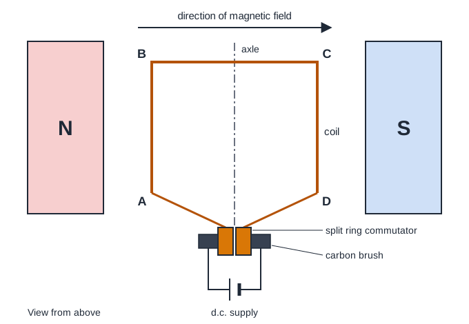
A simple d.c. motor seen from above. A north pole is on the left and a south pole on the right, with an arrow above showing the direction of the magnetic field from left to right. Between the poles, a rectangular coil lies flat. Its sides AB and DC run along the axle, which goes up the middle of the drawing, and side BC joins them at the top. The ends of the coil at A and D are joined to the two halves of a split ring commutator on the axle. Two carbon brushes press on the commutator and are wired to a d.c. supply.

Model answer

Side BC is parallel to the magnetic field, so the current in it flows along the field lines, and there is no force on a current that is parallel to the field.

Explanation

There is a force on a current-carrying wire only when the current has a part at right angles to the field; the force is greatest when the wire is at right angles to the field, as sides AB and CD are. In this position side BC lies along the field, so the force on it is zero. A common error is to think that no current flows in BC, but the current flows all the way round the coil.

Mark scheme
  1. 1 mark

    (the current in) side BC is parallel to the magnetic field / BC lies along the field lines (1)

    accept 'BC is not at right angles to the field' or 'the current in BC is in the same direction as (or the opposite direction to) the field'. Do not accept 'BC is not between the magnets' or 'no current flows in BC' (the current flows all the way round the coil). Ignore references to Fleming's left-hand rule without the idea of the current being parallel to the field.
Question 2

2 marks

Sam connects a small d.c. motor to a variable power supply. He measures the speed of the motor at different potential differences (p.d.s).

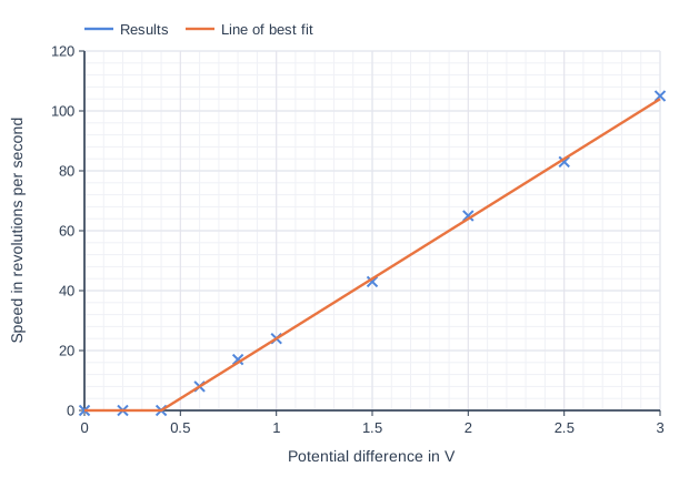
The graph shows his results and his line of best fit.

Explain why the motor does not turn at all below about 0.4 V, and why its speed increases as the p.d. is increased above this.

Line graph of speed in revolutions per second (y-axis, 0 to 120) against Potential difference in V (x-axis, 0 to 3). "Results" is shown as plotted points only (no line), at (0, 0), (0.2, 0), (0.4, 0), (0.6, 8), (0.8, 17), (1, 24), (1.5, 43), (2, 65), (2.5, 83), (3, 105). "Line of best fit" joins the points (0, 0), (0.4, 0), (3, 104).

Model answer

Below about 0.4 V the current in the coil is very small, so the forces on the sides of the coil are small. Their moment about the axle is less than the opposing moment of the friction at the axle and brushes, so the coil cannot start to turn.
Above this p.d., a larger p.d. drives a larger current through the coil. The forces on the coil (F = B × I × l) and their moment are then larger, so the coil turns faster before friction and air resistance balance it.

Explanation

The motor only starts when the turning effect of the forces on the coil is bigger than the turning effect of friction, so there is a minimum p.d. below which nothing happens. Above it, a larger p.d. gives a larger current, larger forces and so a faster motor. Saying that there is no current below 0.4 V is a common error: a small current does flow, but its forces are too small to start the coil.

Mark scheme
  1. 1 mark

    (below about 0.4 V) the current is so small that the moment of the forces on the coil is not large enough to overcome friction (at the axle / brushes) (1)

    Mark the two points independently. accept 'the turning effect of the forces on the coil is smaller than the turning effect of friction'. Do not accept 'there is no current' or 'there is no force' below 0.4 V.

  2. 1 mark

    a larger p.d. gives a larger current in the coil, so larger forces on the coil / a larger moment, so it turns faster (1)

    accept 'F = B × I × l, so a larger current gives a larger force'. accept 'the motor speeds up until friction and air resistance balance the larger moment, at a higher speed'. The link from p.d. to current to force (or moment) is needed.

Question 3

3 marks

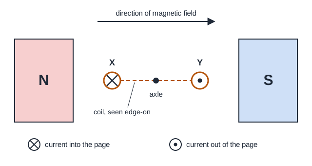
The figure shows the coil of a simple d.c. motor, seen end-on along its axle. The coil is between the poles of a magnet. At this moment, the current in side X of the coil is into the page and the current in side Y is out of the page.

Deduce whether the coil starts to turn clockwise or anticlockwise, as seen in the figure. Explain your answer.

End view of the coil of a d.c. motor, seen along the axle. A north pole is on the left and a south pole is on the right, with an arrow above showing the direction of the magnetic field from left to right. The coil is horizontal, seen edge-on as a dashed line with the axle at its centre. Side X of the coil, on the left, is marked with a cross, meaning current into the page. Side Y, on the right, is marked with a dot, meaning current out of the page. A key explains the cross and the dot.

Model answer

The field between the poles points from N to S, to the right. Using Fleming's left-hand rule for side X (first finger to the right for the field, second finger into the page for the current), the thumb points down, so the force on X is downwards. The current in Y is in the opposite direction, so the force on Y is upwards. X is pushed down on the left of the axle and Y is pushed up on the right, so both forces turn the coil anticlockwise.

Explanation

The current flows one way along one side of the coil and back the other way along the other side, so the forces on the two sides are in opposite directions. Because the sides are on opposite sides of the axle, these opposite forces have moments in the same direction, so the coil turns. Using the right hand instead of the left, or mixing up which finger shows the field and which the current, gives the wrong direction.

Mark scheme
  1. 1 mark

    the force on side X is downwards / towards the bottom of the page (1)

    An explanation linking the direction of the force on each side (from Fleming's left-hand rule) to the direction of turning. Mark the three points independently. accept a clear description, e.g. 'X is pushed down and Y is pushed up'.

  2. 1 mark

    the force on side Y is upwards / towards the top of the page (1)

    Do not accept 'to the left' or 'to the right' for either force (the forces are at right angles to the field).

  3. 1 mark

    (so the coil turns) anticlockwise (1)

    A correct direction of turning with no reasoning scores this mark only. Do not accept clockwise.

Question 4

4 marks

The coil of a model d.c. motor has 50 turns, so each long side of the coil contains 50 lengths of wire. Each long side is 4.0 cm long and lies at right angles to a uniform magnetic field of magnetic flux density 0.20 T. The coil is 3.0 cm wide, and the axle runs along the middle of the coil, parallel to the long sides.

The current in the coil is 1.5 A. The plane of the coil is parallel to the magnetic field.

Calculate the total moment of the forces on the coil about the axle.

Use the equation
F = B × I × l
for the force on one wire.

Model answer

Force on one wire: F = B × I × l = 0.20 × 1.5 × 0.040 = 0.012 N
Each long side contains 50 wires, so the force on each side = 50 × 0.012 = 0.60 N
Each side is half the width of the coil from the axle: 3.0 cm ÷ 2 = 1.5 cm = 0.015 m
moment of one force = 0.60 × 0.015 = 0.0090 N m
The two forces turn the coil the same way, so total moment = 2 × 0.0090 = 0.018 N m

Explanation

Each of the 50 turns puts one wire along each long side, so the force on a side is 50 times the force on one wire. With the plane of the coil parallel to the field, the forces act at right angles to the coil, so their perpendicular distance from the axle is half the coil's width, and the moments of the two forces add. Common errors are leaving out the number of turns, using the full width for each force, and not converting centimetres to metres.

Mark scheme
  1. 1 mark

    (force on one wire =) 0.20 × 1.5 × 0.040 = 0.012 (N) (1)

    An answer of 0.018 N m with no working scores 4 marks. The length must be in metres for this mark; later marking points may be awarded by ecf from an unconverted length.

  2. 1 mark

    (force on each long side =) 50 × 0.012 = 0.60 (N) (1)

    allow ecf from marking point 1.

  3. 1 mark

    (moment of the force on one side =) 0.60 × 0.015 = 0.0090 (N m) (1)

    The perpendicular distance from the axle to each side is half the width of the coil, 1.5 cm = 0.015 m. allow ecf from marking point 2. Alternative: the two equal and opposite forces are 0.030 m apart, so total moment = 0.60 × 0.030, which scores marking points 3 and 4.

  4. 1 mark

    (total moment = 2 × 0.0090 =) 0.018 (N m) (1)

    accept 1.8 × 10⁻² N m or 1.8 N cm. allow ecf from marking point 3. An answer of 3.6 × 10⁻⁴ N m (the 50 turns left out) scores 3 marks. An answer of 0.036 N m (each force multiplied by the full width, 0.030 m, and then doubled) scores 2 marks (marking points 1 and 2). An answer of 0.018 to any other power of ten (e.g. 180, from lengths left in cm) scores 3 marks.

Ready to try the rest? Every answer you write is marked against the mark scheme, so you can see exactly where the marks are.

Study Helper Hints first, answers after you try

Stuck on this one? Ask for a hint and I’ll point you in the right direction, without giving the answer away. Once you’ve checked your answer, I’ll show you how the marks are awarded.