Level:
Correct: 0
Incorrect: 0
Marks: 0/0
Exam Practice
Course:
Topics:
Edexcel GCSE Physics (Paper 2) Smart practice A mixed round aimed at your weak spots
Unit 1
Key concepts of physics
Unit 8
Energy - forces doing work
Unit 9
Forces and their effects
Unit 10
Electricity and circuits
Unit 11
Static electricity
Unit 12
Magnetism and the motor effect
Unit 13
Electromagnetic induction
Unit 14
Particle model
Unit 15
Forces and matter
Avg
score:
–
Topics
done:
0/34

Circuit symbols, series and parallel circuits

Practise 15 exam-style questions on Circuit symbols, series and parallel circuits for Edexcel GCSE Physics (Paper 2). Write your answer as you would in the exam and get it marked in seconds against the mark scheme, point by point, with the Study Helper on hand if you get stuck.

  • 15 questions
  • 1–6 marks each
  • Instant marking
  • No sign-up needed
15 questions, marked as you go

Sample questions with model answers

Here are 4 of the questions in this topic, each with a model answer, an explanation of why it earns the marks and the mark scheme an examiner would use.

Question 1

1 mark

The circuit symbols for a light-dependent resistor (LDR) and a light-emitting diode (LED) both include two small arrows.

Which of these describes the arrows in the two symbols?

Choose your answer.

  • A both point in towards the symbol
  • B both point out away from it
  • C LDR: point in; LED: point out
  • D LDR: point out; LED: point in

Model answer

C - the arrows point in towards the LDR symbol and out away from the LED symbol.

Explanation

The arrows show which way the light travels: into an LDR, because light affects its resistance, and out of an LED, because it emits light. Thinking about the direction of the light is the easiest way to avoid mixing up the two symbols.

Mark scheme
  1. 1 mark

    C / LDR: point in; LED: point out (1)

    The only correct answer is C: the arrows on the LDR symbol point towards it because light falling on it changes its resistance, and the arrows on the LED symbol point away from it because it gives out light. A is not correct because the arrows on the LED symbol point outwards; B is not correct because the arrows on the LDR symbol point inwards; D is not correct because it describes the two symbols the wrong way round. Accept the letter or the option. If more than one option is given, do not award the mark.
Question 2

2 marks

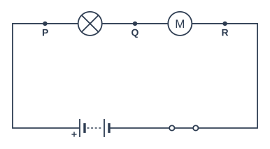
Figure 1 shows a series circuit. P, Q and R are points on the wires.

A student uses a voltmeter to measure:
- the potential difference across the motor
- the potential difference across the lamp and the motor together.

For each measurement, state the two points that the voltmeter should be connected to.

Circuit diagram. All the components are connected in series in a single loop. Going round the loop from the + terminal of the battery: point P; then a lamp; then point Q; then a motor; then point R; then a closed switch; and back to the − terminal of the battery.

Model answer

To measure the potential difference across the motor, the voltmeter is connected to points Q and R. To measure the potential difference across the lamp and the motor together, it is connected to points P and R.

Explanation

A voltmeter is connected in parallel with whatever it measures, so its two leads go to the points on either side: Q and R are on either side of the motor, and P and R are on either side of both components. Common mistakes are choosing P and Q, which measures the lamp only, or connecting the voltmeter in series.

Mark scheme
  1. 1 mark

    (across the motor) Q and R (1)

    Accept in either order (R and Q). Do not accept P and Q (that is across the lamp) or P and R for this measurement.

  2. 1 mark

    (across the lamp and the motor together) P and R (1)

    Accept in either order (R and P). Each answer must be matched to the correct measurement.

Question 3

3 marks

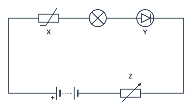
Figure 1 shows a circuit diagram.

Name component X, component Y and component Z.

Circuit diagram. All the components are connected in series in a single loop. Going round the loop from the + terminal of the battery: component X (drawn as a rectangle with a diagonal line through it that ends in a short horizontal tail at the bottom); then a lamp; then component Y (drawn as a circle containing a triangle with a bar across its point) pointing forwards (its triangle points the way we are going round); then component Z (drawn as a rectangle with a diagonal arrow drawn through it); and back to the − terminal of the battery.

Model answer

X is a thermistor, Y is a diode and Z is a variable resistor.

Explanation

A thermistor is drawn as a resistor rectangle with a diagonal line through it that ends in a short horizontal tail, while a variable resistor has a diagonal arrow through the rectangle. A diode is a triangle with a bar across its point inside a circle; an LED looks the same but has two arrows pointing away from it. Students often confuse the thermistor and variable resistor symbols.

Mark scheme
  1. 1 mark

    (X) thermistor (1)

    Each name must be matched to its letter. Accept 'NTC thermistor' / 'temperature-dependent resistor'. Do not accept variable resistor or LDR.

  2. 1 mark

    (Y) diode (1)

    Do not accept LED / light-emitting diode (the LED symbol also has two arrows pointing away from it) or lamp.

  3. 1 mark

    (Z) variable resistor (1)

    Accept rheostat. Do not accept resistor (without 'variable') or thermistor.

Question 4

4 marks

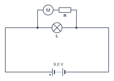
Figure 1 shows the circuit of a toy car. Lamp L is in one branch. The motor and resistor R are connected in series in the other branch. The battery has a potential difference of 9.0 V.

The potential difference across the motor is 5.5 V.

State the potential difference across lamp L, and calculate the potential difference across resistor R.

Explain your answers.

Circuit diagram. Going round the loop from the + terminal of the battery (labelled 9.0 V): two branches in parallel (one branch has lamp L; the other branch has a motor then resistor R); and back to the − terminal of the battery.

Model answer

The potential difference across lamp L is 9.0 V, because L is in a branch connected directly across the battery, and each branch of a parallel circuit has the same p.d. as the supply. The other branch also has 9.0 V across it, and this is shared between the motor and R because they are in series.
p.d. across R = 9.0 − 5.5 = 3.5 V

Explanation

Each parallel branch has the full supply p.d. across it, and components in series within a branch share that p.d. So the lamp has 9.0 V and R has 9.0 − 5.5 = 3.5 V. A common error is to think the lamp has only part of the 9.0 V, or that the p.d. is shared between the two branches.

Mark scheme
  1. 1 mark

    (p.d. across lamp L =) 9.0 V (1)

    Accept 9 V.

  2. 1 mark

    because lamp L is in parallel with the battery / connected directly across the battery / each parallel branch has the same p.d. as the battery (1)

    Accept 'the lamp's branch has the full supply p.d. across it'.

  3. 1 mark

    the 9.0 V across the other branch is shared between the motor and R (because they are in series) (1)

    Accept 'p.d. across R + p.d. across motor = 9.0 V'.

  4. 1 mark

    (p.d. across R = 9.0 − 5.5 =) 3.5 V (1)

    Award this mark for 3.5 V with or without working; the second and third points need the explanations. Do not accept 14.5 V.

Ready to try the rest? Every answer you write is marked against the mark scheme, so you can see exactly where the marks are.

Study Helper Hints first, answers after you try

Stuck on this one? Ask for a hint and I’ll point you in the right direction, without giving the answer away. Once you’ve checked your answer, I’ll show you how the marks are awarded.