
Level:
Correct: 0
Incorrect: 0
Marks: 0/0
Exam Practice
Course:
Topics:
Avg
score:
–
Topics
done:
0/22

Current-voltage graphs, LDRs and thermistors

Practise 16 exam-style questions on Current-voltage graphs, LDRs and thermistors for Edexcel GCSE Combined Science (Foundation Physics Paper 2). Write your answer as you would in the exam and get it marked in seconds against the mark scheme, point by point, with the Study Helper on hand if you get stuck.

  • 16 questions
  • 1–6 marks each
  • Instant marking
  • No sign-up needed
16 questions, marked as you go

Sample questions with model answers

Here are 4 of the questions in this topic, each with a model answer, an explanation of why it earns the marks and the mark scheme an examiner would use.

Question 1

1 mark

A light-dependent resistor (LDR) is on a desk in a brightly lit classroom. Arjun covers the LDR with his hand, so that no light reaches it.

What happens to the resistance of the LDR?

Choose your answer.

  • A it increases
  • B it decreases
  • C it stays the same
  • D it becomes zero

Model answer

A - it increases

Explanation

The resistance of a light-dependent resistor decreases as the light intensity on it increases. Covering the LDR makes it dark, so the light intensity falls and its resistance rises. A common mistake is to confuse the LDR with a thermistor, or to think its resistance falls in the dark.

Mark scheme
  1. 1 mark

    A / it increases

    The only correct answer is A: the resistance of an LDR decreases as the light intensity increases, so when the light intensity falls (the LDR is in the dark) its resistance increases. B is not correct because the resistance of an LDR only decreases when more light falls on it; C is not correct because the resistance of an LDR depends on the light intensity; D is not correct because the resistance of an LDR is never zero, and in the dark it is very high. Accept the letter or the option. If more than one option is given, do not award the mark.
Question 2

2 marks

Owen investigates how the current in a diode changes as he increases the potential difference across it from 0 V to 0.8 V.

His teacher tells him to take more readings between 0.6 V and 0.8 V than between 0 V and 0.5 V.

Explain why.

Model answer

Below about 0.5 V the current in the diode is zero and does not change, so a few readings are enough. Above about 0.6 V the current rises very steeply for small increases in potential difference, so many readings close together are needed to show the shape of the curve accurately.

Explanation

In the forward direction a diode has a very high resistance until the potential difference reaches about 0.6 V; then its resistance falls and the current rises steeply. Readings should be closest together where the graph changes most quickly. Answers that only say 'to be more accurate' do not explain why this range needs more readings.

Mark scheme
  1. 1 mark

    between 0 V and 0.5 V the current is (almost) zero / does not change

    An explanation linking the two points. accept 'the diode does not conduct until about 0.6 V' or 'the diode has a very high resistance at low potential differences'.

  2. 1 mark

    between 0.6 V and 0.8 V the current increases rapidly / steeply (for small changes in potential difference), so more readings are needed to show the shape of the graph (accurately)

    Both the rapid change in current and the idea of showing the shape (or plotting the curve accurately) are needed. accept 'the resistance of the diode falls quickly in this range, so readings close together are needed to plot the curve'. Ignore 'to make it more accurate' or 'to make it a fair test' with no reason.

Question 3

3 marks

Zara tests a small filament lamp. When the potential difference across the lamp is 6.0 V, the current in it is 0.40 A.

Zara says: 'The resistance of the lamp is 15 Ω. So when the potential difference across the lamp is 1.5 V, the current will be a quarter of 0.40 A, which is 0.10 A.'

When Zara tests the lamp at 1.5 V, the current is 0.19 A.

Explain why the current at 1.5 V is larger than Zara predicted.

Model answer

Zara assumed that the resistance of the lamp stays at 15 Ω, but it does not: at 1.5 V the resistance is only 1.5 ÷ 0.19 = 7.9 Ω. At 1.5 V the current is smaller, so it does not heat the filament as much, and the filament is cooler than it is at 6.0 V. The resistance of a metal filament is lower when it is cooler, so the current at 1.5 V is larger than Zara predicted.

Explanation

Zara's prediction only works if the current is directly proportional to the potential difference, which needs a constant resistance. The resistance of a filament lamp depends on the temperature of the filament, and a cooler filament has a lower resistance, so at low potential differences the current is larger than a constant 15 Ω would give. A common mistake is to say that the resistance is higher at low potential differences.

Mark scheme
  1. 1 mark

    the resistance of the lamp is not constant / is lower at 1.5 V than at 6.0 V (so Zara was wrong to use 15 Ω)

    An explanation linking the three points. accept a calculation showing that the resistance at 1.5 V is less than 15 Ω: 1.5 ÷ 0.19 = 7.9 Ω. accept 'Zara assumed that the resistance stays the same'. Ignore 'the current is not directly proportional to the potential difference' on its own (it does not say why the current is larger). Do not accept 'the resistance is higher at 1.5 V'.

  2. 1 mark

    at 1.5 V the current is smaller, so the filament is cooler / at a lower temperature (than at 6.0 V)

    accept 'the filament does not get as hot at 1.5 V' or 'at 6.0 V the larger current heats the filament more'. Ignore 'the lamp is dimmer' on its own.

  3. 1 mark

    the resistance of the (metal) filament is lower when it is cooler / increases as its temperature increases

    accept 'a hotter filament has a higher resistance'. accept 'when the filament is cooler its ions vibrate less, so the electrons collide with them less often'. Do not accept 'the resistance of the filament decreases as its temperature increases'.

Question 4

4 marks

Isla connects a diode in series with a 150 Ω resistor, an ammeter and a battery. The diode is connected so that it conducts. The ammeter reads 20 mA.

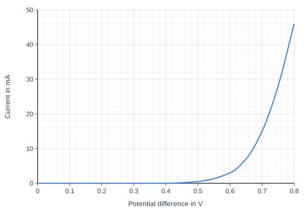
The graph shows how the current in the diode varies with the potential difference across it.

The potential difference of the battery is shared between the diode and the resistor.

Calculate the potential difference of the battery.

Use the graph and the equation

V = I × R

Line graph of current in mA (y-axis, 0 to 50) against Potential difference in V (x-axis, 0 to 0.8). The line is a smooth curve through (0, 0), (0.2, 0), (0.4, 0), (0.5, 0.5), (0.6, 3), (0.65, 7), (0.7, 15), (0.75, 28), (0.8, 46).

Model answer

From the graph, when the current is 20 mA the potential difference across the diode is 0.72 V.
Potential difference across the resistor: V = I × R = 0.020 × 150 = 3.0 V
Potential difference of the battery = 3.0 + 0.72 = 3.7 V

Explanation

Go across from 20 mA on the current axis to the curve and down to read the potential difference across the diode. Convert 20 mA to 0.020 A before using V = I × R for the resistor. In a series circuit the potential differences across the components add up to the potential difference of the battery. Common errors are forgetting to add the potential difference across the diode and using 20 instead of 0.020.

Mark scheme
  1. 1 mark

    reading from the graph: potential difference across the diode = 0.72 (V); or a correct final answer of 3.7 V with no working

    An answer of 3.7 V with no working scores 4 marks. accept 0.70 to 0.74 (V). Leaving the current in mA (20 × 150 = 3000 V, giving 3000.7 V for the battery) is a power of ten error and scores marking points 1 and 2 (2 marks).

  2. 1 mark

    substitution, with the current in A: (V =) 0.020 × 150; or a correct final answer of 3.7 V with no working

    The conversion of 20 mA to 0.020 A may be seen in the substitution. allow 20 × 150 (current left in mA, a power of ten error) for this mark only.

  3. 1 mark

    potential difference across the resistor = 3.0 (V); or a correct final answer of 3.7 V with no working

    3000 V (current left in mA) does not score this mark or marking point 4.

  4. 1 mark

    evaluation: (potential difference of the battery =) 3.0 + 0.72 = 3.7 (V)

    accept 3.70 to 3.74 (V) from a reading in the accepted range. allow ecf: their potential difference across the resistor + their reading, but not from the power of ten error (3000 V). An answer of 3.0 V (the resistor only) scores marking points 2 and 3. An answer of 0.72 V (the diode only) scores marking point 1.

Ready to try the rest? Every answer you write is marked against the mark scheme, so you can see exactly where the marks are.

Study Helper Hints first, answers after you try

Stuck on this one? Ask for a hint and I’ll point you in the right direction, without giving the answer away. Once you’ve checked your answer, I’ll show you how the marks are awarded.