
Level:
Correct: 0
Incorrect: 0
Marks: 0/0
Exam Practice
Course:
Topics:
Avg
score:
–
Topics
done:
0/22

Circuit symbols, series and parallel circuits

Practise 16 exam-style questions on Circuit symbols, series and parallel circuits for Edexcel GCSE Combined Science (Foundation Physics Paper 2). Write your answer as you would in the exam and get it marked in seconds against the mark scheme, point by point, with the Study Helper on hand if you get stuck.

  • 16 questions
  • 1–6 marks each
  • Instant marking
  • No sign-up needed
16 questions, marked as you go

Sample questions with model answers

Here are 4 of the questions in this topic, each with a model answer, an explanation of why it earns the marks and the mark scheme an examiner would use.

Question 1

1 mark

Some circuit symbols include a circle and some do not.

Which of these four components is drawn WITH a circle as part of its circuit symbol?

Choose your answer.

  • A cell
  • B thermistor
  • C ammeter
  • D variable resistor

Model answer

C - ammeter.

Explanation

Meters (ammeters and voltmeters), lamps and motors are drawn as circles with a letter or a cross inside. A cell is two parallel lines, and resistors, thermistors and variable resistors are all based on a rectangle. The thermistor and variable resistor symbols are often confused: the variable resistor's diagonal line ends in an arrow, and the thermistor's ends in a flat tail.

Mark scheme
  1. 1 mark

    C / ammeter

    The only correct answer is C: an ammeter is drawn as a circle with the letter A inside it. A is not correct because a cell is drawn as a long, thin line and a short, thick line, with no circle. B is not correct because a thermistor is drawn as a rectangle with a diagonal line through it that has a short flat tail at one end, with no circle. D is not correct because a variable resistor is drawn as a rectangle with a diagonal arrow through it, with no circle. Accept the letter or the option. If more than one option is given, do not award the mark.
Question 2

2 marks

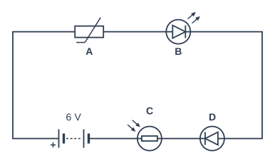
The diagram shows a circuit with four components, labelled A, B, C and D.

Give the letter of the LDR (light-dependent resistor).

Give the letter of the diode.

Circuit diagram. All the components are connected in series in a single loop. Going round the loop from the + terminal of the battery (labelled 6 V): component A (drawn as a rectangle with a diagonal line through it that ends in a short horizontal tail at the bottom); then component B (drawn as a circle containing a triangle with a bar across its point, with two small arrows pointing away from the circle) pointing forwards (its triangle points the way we are going round); then component D (drawn as a circle containing a triangle with a bar across its point) pointing forwards (its triangle points the way we are going round); then component C (drawn as a small rectangle inside a circle, with two arrows pointing in towards the circle); and back to the − terminal of the battery.

Model answer

The LDR is C.
The diode is D.

Explanation

An LDR is drawn as a resistor (rectangle) inside a circle with two arrows pointing in, showing light falling on it. A diode is a triangle pointing at a bar. An LED uses the same triangle and bar but has two arrows pointing out, showing the light it gives out, so B is the LED, not the plain diode. A is a thermistor (a resistor symbol with a diagonal line that has a flat tail).

Mark scheme
  1. 1 mark

    (LDR) C

    C is the LDR: a small rectangle inside a circle with two arrows pointing in towards it. Do not accept A (thermistor) or B (LED). If more than one letter is given for the LDR, do not award this mark.

  2. 1 mark

    (diode) D

    D is the diode: a triangle with a bar across its point, with no arrows. Do not accept B: B is an LED (it has two arrows pointing away from it). If more than one letter is given for the diode, do not award this mark.

Question 3

2 marks

Lowri uses a digital voltmeter to measure the potential difference across a lamp in a circuit. She connects the voltmeter in parallel with the lamp.

The reading on the voltmeter is −2.4 V.

Explain why the reading has a minus sign, and describe how Lowri should change the connections of the voltmeter to get a reading of 2.4 V.

Model answer

The minus sign shows that the voltmeter is connected the wrong way round: its positive terminal is connected to the side of the lamp that is nearer the negative terminal of the cell. Lowri should swap the two leads over, so that the voltmeter's + terminal is connected to the side of the lamp nearer the + terminal of the cell, still in parallel with the lamp. The reading will then be 2.4 V.

Explanation

Meters have a positive and a negative terminal, just like cells. The + terminal of the meter should be connected to the side of the component nearer the + terminal of the supply. A digital meter connected the wrong way round still shows the size of the potential difference but adds a minus sign. The voltmeter is already in parallel, so the fix is to swap its leads, not to move it.

Mark scheme
  1. 1 mark

    the voltmeter is connected the wrong way round / its positive (+) and negative (−) terminals are reversed / its + terminal is connected to the side of the lamp nearer the − terminal of the cell (battery)

    accept the leads (wires) are the wrong way round / the + and − connections are swapped. Do not accept 'it is connected in series' (the question says it is in parallel) or 'the lamp is broken'.

  2. 1 mark

    swap the two connections (leads) of the voltmeter over / connect the + terminal of the voltmeter to the side of the lamp nearer the + terminal of the cell (battery), keeping it in parallel with the lamp

    accept 'turn the voltmeter round' / 'reverse the leads'. Do not accept 'connect it in series' or 'move it across the cell'.

Question 4

4 marks

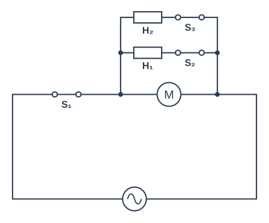
The diagram shows the circuit of a fan heater. The motor turns the fan. H₁ and H₂ are heating elements, drawn as resistors. S₁, S₂ and S₃ are switches.

The fan heater has three settings:
- cool: the fan only
- warm: the fan and one heating element
- hot: the fan and both heating elements.

Explain how the switches are used to give each of the three settings.

Circuit diagram. Going round the loop from the a.c. power supply: switch S₁ (closed); then three branches in parallel (the first branch has a motor; the second branch has resistor H₁ then switch S₂ (closed); the third branch has resistor H₂ then switch S₃ (closed)); and back to the supply.

Model answer

S₁ is in the main part of the circuit, in series with all three branches, so it must be closed for any setting; opening S₁ switches everything off.
Cool: close S₁ and leave S₂ and S₃ open. Only the motor's branch is a complete circuit, so only the fan works.
Warm: close S₁ and S₂ (or S₁ and S₃). There is now a current in one heating element as well as the motor.
Hot: close S₁, S₂ and S₃, so there is a current in both heating elements and the motor.
This works because the motor and each heating element are in separate parallel branches, so each heating element's switch only switches its own branch on or off.

Explanation

A switch in the main part of a circuit controls everything, while a switch in one parallel branch controls only that branch. Here S₂ and S₃ are in the heating elements' branches, so they choose how many elements are on, and the motor runs whenever S₁ is closed. A common mistake is to say S₂ or S₃ on its own can switch the heater on: nothing works unless S₁ is closed.

Mark scheme
  1. 1 mark

    S₁ is in the main part of the circuit / in series with all the branches, so S₁ must be closed for every setting / opening S₁ switches everything off

    Any four of the five marking points, max 4. accept S1 for S₁ (and S2, S3 for S₂, S₃) throughout. accept 'all the current passes through S₁'.

  2. 1 mark

    cool: S₁ closed with S₂ and S₃ open, so only the motor's branch is a complete circuit / there is a current only in the motor

    'Close S₁' with no reference to S₂ and S₃ being open does not score this point.

  3. 1 mark

    warm: S₁ and one of S₂ or S₃ closed (the other open), so there is a current in one heating element (as well as the motor)

    accept S₁ and S₂ closed (S₃ open), or S₁ and S₃ closed (S₂ open).

  4. 1 mark

    hot: S₁, S₂ and S₃ all closed, so there is a current in both heating elements and the motor

    accept 'close all three switches'.

  5. 1 mark

    each heating element (and the motor) is in its own (parallel) branch, so its switch only switches that branch on or off / the other branches still have a complete circuit

    accept the heating elements are in parallel so they can be switched on and off separately / independently. Do not accept 'the heaters are in series'.

Ready to try the rest? Every answer you write is marked against the mark scheme, so you can see exactly where the marks are.

Study Helper Hints first, answers after you try

Stuck on this one? Ask for a hint and I’ll point you in the right direction, without giving the answer away. Once you’ve checked your answer, I’ll show you how the marks are awarded.