
Level:
Correct: 0
Incorrect: 0
Marks: 0/0
Exam Practice
Course:
Topics:
OCR GCSE Physics (Paper 3) Smart practice A mixed round aimed at your weak spots
Unit 1
Matter
Unit 2
Forces
Unit 3
Electricity
Unit 4
Magnetism and magnetic fields
Unit 9
Practical skills
Avg
score:
–
Topics
done:
0/36

Investigating components and their graphs

Practise 16 exam-style questions on Investigating components and their graphs for OCR GCSE Physics (Paper 3). Write your answer as you would in the exam and get it marked in seconds against the mark scheme, point by point, with the Study Helper on hand if you get stuck.

  • 16 questions
  • 1–6 marks each
  • Instant marking
  • No sign-up needed
16 questions, marked as you go

Sample questions with model answers

Here are 4 of the questions in this topic, each with a model answer, an explanation of why it earns the marks and the mark scheme an examiner would use.

Question 1

1 mark

A student draws a thick line on paper with a soft pencil. The line has the same width and thickness all along its length, and it conducts electricity.

With two crocodile clips 4.0 cm apart on the line, the resistance between the clips is 12 kΩ.

The student moves the clips so that they are 10.0 cm apart.

What is the resistance between the clips now?

Choose your answer.

  • A 4.8 kΩ
  • B 18 kΩ
  • C 30 kΩ
  • D 120 kΩ

Model answer

C. Resistance per cm = 12 ÷ 4.0 = 3.0 kΩ per cm, so for 10.0 cm: 3.0 × 10.0 = 30 kΩ.

Explanation

A pencil line behaves like a wire: if its width and thickness stay the same, its resistance is proportional to its length, so 2.5 times the length gives 2.5 times the resistance. A common error is to work out only the resistance of the extra length added.

Mark scheme
  1. 1 mark

    C / 30 kΩ

    The only correct answer is C: for a conductor of the same width and thickness, the resistance is proportional to the length: 12 kΩ ÷ 4.0 cm = 3.0 kΩ per cm, so 10.0 cm has a resistance of 30 kΩ. A is not correct because 4.8 kΩ (12 × 4.0 ÷ 10.0) assumes the resistance decreases as the length increases; B is not correct because 18 kΩ (3.0 × 6.0) is the resistance of the extra 6.0 cm only; D is not correct because 120 kΩ (12 × 10) multiplies by the new length instead of by the ratio of the lengths. ALLOW the letter or the option. If more than one option is given, do not award the mark.
Question 2

2 marks

A student investigates a diode connected in the forward direction. She plots her results with potential difference on the vertical (y) axis and current on the horizontal (x) axis.

Describe the shape of her graph, and explain what it shows about how the resistance of the diode changes as the current increases.

Model answer

The graph rises very steeply from the origin at first, because the p.d. increases while the current is still very small. Once the p.d. reaches about 0.6–0.7 V, the line becomes much less steep and almost levels off: the current can increase a lot for very little increase in p.d.
Resistance = p.d. ÷ current, so the resistance of the diode is very large at very small currents and decreases as the current increases.

Explanation

With the axes this way round, p.d. ÷ current for any point on the line is the resistance. A diode hardly conducts until the forward p.d. reaches about 0.6 V, and then the current rises steeply, so on these axes the curve rises steeply and then levels off. Do not confuse this graph with the usual I–V characteristic, which has current on the vertical axis.

Mark scheme
  1. 1 mark

    the line rises very steeply from the origin (the p.d. increases while the current is still very small) and then becomes much less steep / almost levels off (at a p.d. of about 0.6–0.8 V) (while the current increases a lot)

    ALLOW a curve whose gradient decreases / that gets less steep. A value for the p.d. is not needed; if one is given, ALLOW any p.d. from 0.5 V to 0.8 V for the level part. DO NOT ALLOW a straight line through the origin / a curve that gets steeper. DO NOT ALLOW the shape of the usual current–p.d. graph (flat along the horizontal axis at first, then rising steeply).

  2. 1 mark

    the resistance (p.d. ÷ current) decreases as the current increases / once the diode conducts, a large current passes for only a small increase in p.d., so its resistance becomes small

    ALLOW the resistance is very large at very small currents and small at larger currents. DO NOT ALLOW the resistance increases.

Question 3

3 marks

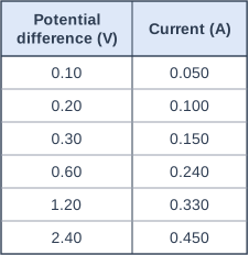
A student measures the current in a small filament lamp at different potential differences. The table shows her results.

The student says:

'The lamp is a linear component at low potential differences, but not at higher potential differences.'

Use calculations of resistance to find the range of potential difference over which the lamp behaves as a linear component.

Table with columns "Potential difference (V)", "Current (A)". Potential difference (V): 0.10; Current (A): 0.050 | Potential difference (V): 0.20; Current (A): 0.100 | Potential difference (V): 0.30; Current (A): 0.150 | Potential difference (V): 0.60; Current (A): 0.240 | Potential difference (V): 1.20; Current (A): 0.330 | Potential difference (V): 2.40; Current (A): 0.450.

Model answer

Resistance = p.d. ÷ current.
0.10 V: 0.10 ÷ 0.050 = 2.0 Ω; 0.20 V: 0.20 ÷ 0.100 = 2.0 Ω; 0.30 V: 0.30 ÷ 0.150 = 2.0 Ω.
0.60 V: 0.60 ÷ 0.240 = 2.5 Ω; 1.20 V: 1.20 ÷ 0.330 = 3.6 Ω; 2.40 V: 2.40 ÷ 0.450 = 5.3 Ω.
The resistance is constant (2.0 Ω) from 0 to 0.30 V, so the lamp behaves as a linear component over this range. Above 0.30 V the resistance increases, so the lamp is non-linear.

Explanation

A component is linear while its resistance stays constant, because then the current is proportional to the p.d. At very small currents the filament hardly warms up, so its resistance stays at the cold value; at larger currents it gets hot and its resistance rises. The data only show that the change happens somewhere between 0.30 V and 0.60 V, so 0.30 V is the safe limit to give.

Mark scheme
  1. 1 mark

    resistance calculated for the readings up to 0.30 V, showing it is the same each time: 0.10 ÷ 0.050 = 0.20 ÷ 0.100 = 0.30 ÷ 0.150 = 2.0 Ω

    Max 1 if no resistance values are calculated. ALLOW current ÷ p.d. = 0.50 for each of these readings. ALLOW 2 Ω.

  2. 1 mark

    resistance calculated for at least one reading above 0.30 V, showing that it is larger, for example 0.60 ÷ 0.240 = 2.5 Ω (or 3.6 Ω at 1.20 V, 5.3 Ω at 2.40 V)

    ALLOW 1.20 ÷ 0.330 = 3.64 Ω and 2.40 ÷ 0.450 = 5.33 Ω.

  3. 1 mark

    the lamp is linear from 0 to 0.30 V (constant resistance / current proportional to p.d.) and non-linear above 0.30 V

    ALLOW up to (about) 0.3 V. ALLOW the range 0.10 V to 0.30 V. DO NOT ALLOW up to 0.60 V or higher.

Question 4

4 marks

A student tests a diode connected in the reverse direction. Her ammeter has a resolution of 0.01 A. For every potential difference from 0 V to −5.0 V, it reads 0.00 A.

She concludes: 'In the reverse direction, the diode has an infinite resistance.'

Her teacher repeats the test with a meter that measures very small currents. At −5.0 V the current is 2.0 μA.

Use the teacher's reading to calculate the diode's resistance at −5.0 V.

Use the equation: potential difference = current × resistance

Evaluate the student's conclusion.

Model answer

Resistance = p.d. ÷ current = 5.0 ÷ (2.0 × 10⁻⁶) = 2.5 × 10⁶ Ω (2.5 MΩ).

The student's conclusion is not correct. The resistance in the reverse direction is very large, but it is not infinite, because a small current does flow. Her ammeter could only show changes of 0.01 A, and 2.0 μA (0.000 002 A) is far too small for it to detect, so the reading of 0.00 A only showed that the current was less than about 0.005 A, not that it was zero.

Explanation

Convert 2.0 μA to 2.0 × 10⁻⁶ A before dividing. A meter reading of zero means only that any current is smaller than the meter can show, so the resolution of the instrument limits the conclusion. A diode has a very high, but finite, resistance in the reverse direction.

Mark scheme
  1. 1 mark

    rearrangement and substitution: (resistance =) 5.0 ÷ (2.0 × 10⁻⁶); or a correct final answer of 2.5 × 10⁶ Ω with no working

    An answer of 2.5 × 10⁶ Ω with no working scores marking points 1 and 2. ALLOW 2.5 MΩ or 2 500 000 Ω. IGNORE a minus sign. ALLOW 1 mark for 2.5 × 10ⁿ with a power-of-ten error, for example 2500 Ω (2.0 μA taken as 2.0 mA).

  2. 1 mark

    evaluation: 2.5 × 10⁶ (Ω)

    ALLOW 2.5E6, 2.5 times 10 to the power 6 or 2.5 MΩ.

  3. 1 mark

    the reverse resistance is very large but not infinite (there is a small current), so the conclusion is not correct

    ALLOW the conclusion is only partly correct: the resistance is very high but it is a finite value.

  4. 1 mark

    the current is much smaller than the resolution of her ammeter, so her ammeter could not detect it / her zero reading only shows that the current was too small for her ammeter to measure

    The teacher's current, 2.0 μA (0.000 002 A), is far below the student's resolution of 0.01 A; her reading of 0.00 A only shows that the current was less than about 0.005 A. ALLOW her ammeter was not sensitive enough / had too low a resolution to measure the current. DO NOT ALLOW 'her ammeter was broken' or 'she made a mistake reading it'.

Ready to try the rest? Every answer you write is marked against the mark scheme, so you can see exactly where the marks are.

Study Helper Hints first, answers after you try

Stuck on this one? Ask for a hint and I’ll point you in the right direction, without giving the answer away. Once you’ve checked your answer, I’ll show you how the marks are awarded.